Setback Control Installation
-31-
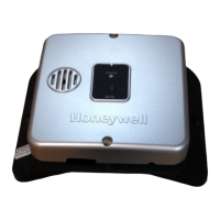
Remove the Setback Control Junction Box Assembly
Step 9: Remove the Setback Control Junction Box Assembly from the top of the water heater, as shown in
Figure 36.
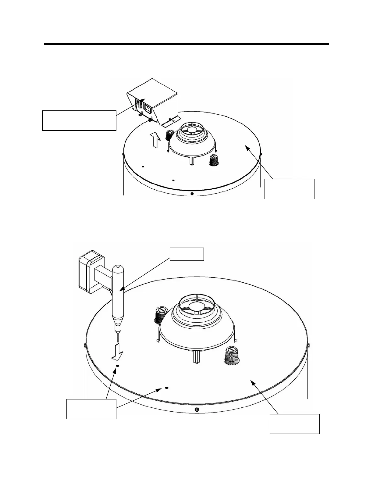
Drill the Setback Control Junction Box Assembly Mounting Holes
Step 10: Using a 1/8” drill bit and drill, drill the (2) screw holes that were marked in Step 8. This is shown
in Figure 37.
Figure 36
Fi
ure 37
Setback Control
Junction Box Assembly
Top of Water
Heater
Top of Water
Heater
Drill
Marked Drill
Locations