Do you have a question about the Bradford White ACCESSORY MODULE and is the answer not in the manual?
Introduces the Accessory Module and lists associated Protection, Performance, and Inlet Shut-off Valve Packages.
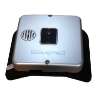
Details items included in the Accessory Module package: transformer, harnesses, and labels.
Details Protection Package components: leak sensor, dam, and wire harness.
Lists Performance Package items: Setback Control and Integrated Mixing Device.
Specifies Inlet Shut-off Valve package parts: the valve and bushings.
Provides diagrams illustrating electrical connections for different gas control types.
Guides for unpacking, determining wire harness, and physically mounting the Accessory Module.
Details for connecting transformer and gas control wire harnesses to the Accessory Module terminals.
Steps for connecting the Accessory Module to WV4460 and WV8840 gas control harnesses.
Instructions for unpacking, preparing, and mounting the Setback Control and its junction box assembly.
Details for connecting the Setback Control wire harness to the Accessory Module terminals.
Directs users to separate instructions for installing and operating the Integrated Mixing Device.
Steps for assembling, connecting wiring, and mounting the Leak Sensor and its components.
Guidance on positioning the dam and sealing gaps for effective leak detection.
Instructions for preparing the water heater, installing the valve, and connecting bushings.
Steps to connect the Inlet Shut-off Valve wire harness to the Accessory Module.
Steps to detach the Setback Control and prepare its backplate for wiring.
Instructions for routing, labeling, stripping, and connecting wires for remote mounting.
Procedure for snapping the Setback Control onto its protective plate after wiring.
Steps for routing wire harnesses and re-installing the Accessory Module cover.
Instructions for plugging in the transformer and observing the Accessory Module's start-up LED.
Guidance on interpreting LED indicators and addressing start-up failures.
Confirm correct operation of the Inlet Shut-off Valve and program the Setback Control.
| Brand | Bradford White |
|---|---|
| Model | ACCESSORY MODULE |
| Category | Water Heater Accessories |
| Language | English |