Setback Control Installation
-38-
Connect the Setback Control Wire Harness and Accessory Module – cont’d
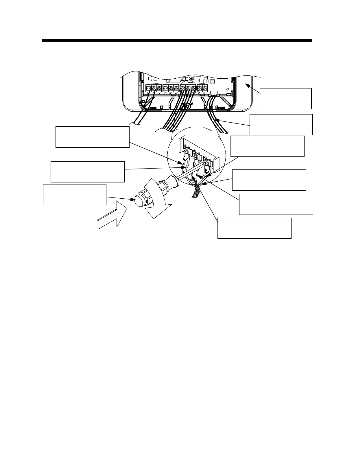
Step 23: Tighten the screw labeled “C/3,” as shown in Figure 50.
The Setback Control installation is complete. Proceed to the
installation sections for the other purchased packages. Or, if finished,
proceed to the Start-up Procedure on page 67.
Figure 50
Accessory
Module
WV4460 Wire Harness
White Wire (if installed)
WV4460 Wire Harness
Black Wire (if installed)
WV4460 Wire Harness
Red Wire (if installed)
Setback Control Wire
Harness Red Wire
Setback Control Wire
Harness Black Wire
Setback Control Wire
Harness White Wire
Philips head
screwdriver
WV8840 Wire
Harness (if installed)