215-1638 Rev. E ECN 14-09-013B
© 2014 Bradley
Page 1 of 3 4/16/2014
P.O. Box 309, Menomonee Falls, WI USA 53052-0309
PHONE 800.BRADLEY (800.272.3539) FAX 262.251.5817
bradleycorp.com
Installation
IMPORTANT!
Read this entire installation manual to ensure proper installation. When
finished with the installation, file this manual with the owner or maintenance
department. Compliance and conformity to local codes and ordinances is
the responsibility of the installer.
Separate parts from packaging and make sure all parts are accounted for
before discarding packaging material. If any parts are missing, do not begin
installation until you obtain the missing parts.
Make sure that all water supply lines have been flushed and then completely
turned off before beginning installation. Debris in supply lines can cause
valves to malfunction.
Product warranties may be found under “Products” on our web site at
bradleycorp.com.
THIS
SIDE
UP
Packing List
•
•
•
•
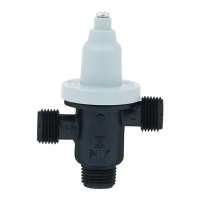
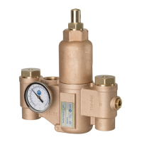
S59-4000
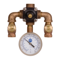
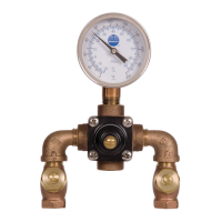
S59-4000A
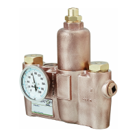
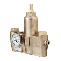
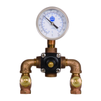
S59-4000BY
Navigator
®
Thermostatic Mixing
Valve for Sinks/Faucets
Supplies and Tools Required ................................. 2
Installation ............................................................. 2
Maintenance and Troubleshooting ......................... 3
Inlet Connections: 1/2" NPT or 3/8" Compression
Outlet Connection: 1/2" NPT or 3/8" Compression
Temperature Range: 95 – 125°F
Maximum Pressure: 125 PSIG
Inlet Temperature, Hot: 120 – 180°F
Inlet Temperature, Cold: 33 – 80°F
Minimum Temperature Differential (from valve set point): 10°F
S59-4000
S59-4000A
(Shown with Optional
Mounting Bracket)
S59-4000BY
(Shown with Optional
Mounting Bracket)
ASSE 1070 & cUPC certified