Factory Setting
Switch Default Options Comments
5
NOTES - Heat Pump Systems
[1] If batteries are installed the 24 Volt AC common connection is optional.
[2] Select O for cool active or B for heat active.
[3] Install a field supplied jumper between the W2 and E terminals if
there is no separate emergency heat relay installed.
Provide disconnect and overload protection as required.
CONV / HP CONV
F / C F
HE / HG HG
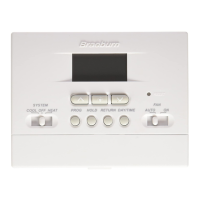
Set Installer Switches
4
CONV Select for conventional systems
HP Select for heat pump systems
F Select for fahrenheit temperature scale
C Select for celsius temperature scale
HG Select for gas heat
HE Select for electric heat
Typical Wiring Configurations
NOTE: The “Installer Switch” option will be configured in the next step.
Heat Pump Systems
1 HEAT / 1 COOL - No Auxiliary Heat
Set Installer Switch to HP
Rh 24 Volt AC Power
Rc Connected to Rh with supplied Jumper Wire
O or B
Changeover Valve [note 2]
Y1 Compressor Relay
G Fan Relay
C 24 Volt AC Transformer Common [note 1]
2 HEAT / 1 COOL - Including Auxiliary Heat (2220NC only)
Set Installer Switch to HP
Rh 24 Volt AC Power
Rc Connected to Rh with supplied Jumper Wire
O or B
Changeover Valve [note 2]
Y1
Compressor Relay (1st stage heating/cooling)
W2 Auxiliary Heat Relay (2nd stage heating)
[note 3]
E Emergency Heat Relay [note 3]
G Fan Relay
C 24 Volt AC Transformer Common [note1]
The Installer switches are located on the back of the thermostat and must
be properly set for this thermostat to operate properly.