EasyManua.ls Logo

Braeburn 3000 User Manual

Braeburn 3000
7 pages
To Next Page IconTo Next Page
Page #1 background imageLoading...
Page #1 background image
©2011 Braeburn Systems LLC • All Rights Reserved. 3000-100-010
1
WARNING
Important Safety Information
Premier Series
Non-Programmable Thermostats
Specifications
Installation
Testing Your New Thermostat
Programming User Settings
Temperature Adjustment
1
2
3
4
5
1
Specifications
Electrical Rating: 24 Volt AC (18-30 Volt AC)
1 amp maximum load per terminal
2 amp total maximum load (all terminals) (Model 3000)
3 amp total maximum load (all terminals) (Model 3200)
Control Range: 45˚ - 90˚ F (7˚ - 32˚ C)
Accuracy: +/- 1˚ F (+/- .5˚ C)
AC Power: 18-30 Volt AC
DC Power: 3.0 Volt DC (2 AA Alkaline batteries included)
Additional Operation
Features
Battery Replacement
Trouble Shooting
Wiring Diagrams
6
7
8
9
Always turn off power to the air conditioning or heating system prior to
installing, removing, cleaning or servicing thermostat.
This thermostat requires either 24 Volts AC Power or two (2) properly installed
“AA” alkaline batteries for normal operation and control of the heating or
cooling system.
This thermostat should only be used as described in this manual. Any other
use is not recommended and will void the warranty.
Specifications
1
Model 3000: Compatibility with low voltage single stage gas, oil or electric
heating or cooling systems, including single stage heat pumps; can also
be used on 250mv to 750mv millivolt heating only systems.
Model 3200: Compatibility with low voltage multi-stage gas, oil or electric
heating or cooling systems, including multi-stage heat pumps.
Terminations, Model 3000: Rc, Rh, B, O, Y, W, G, C
Terminations, Model 3200: R, O, B, C, Y1, Y2, E/W1, W2, G, L
cont.
Replacing Existing Thermostat
Installation
2
1. Always turn off power to the air conditioning or heating system prior to
removing existing thermostat.
2. Remove the cover of your old thermostat and locate the wire terminals.
Do not remove wires from terminals until step 3 is completed.
3. Using small pieces of masking tape, label wires prior to removal from
terminals. Use the chart below to determine the new terminal designations
for your new thermostat.
Old Terminal from
Existing Thermostat
New Terminal for
New Thermostat
(Model 3000)
New Terminal for
New Thermostat
(Model 3200)
Terminal
Description
V or Rc Rc Cooling
Transformer
M, 4, Rh, or R Rh Heating
Transformer
R, V-VR or VR-R R 24 VAC
G or F G G Fan Control
H, W or 4 W Heating Control
W1, W2, W-U or E E/W1 Emergency Heat /
1st Stage Heat
W2 W2 2nd Stage Heat
Y Y Cooling Control
Y, Y1 or M Y1 1st Stage
Compressor
Y2 Y2 2nd Stage
Compressor
B B B Reversing Valve
(Heating)
O O O Reversing Valve
(Cooling)
C C C 24 VAC Common
L or X L System Status LED
4. After labeling and removing all wires from terminals, unscrew the existing
thermostat sub-base from wall. Secure wires to prevent them from slipping into
the hole in the wall.
MODEL
3000
MODEL
3200
Multi-Stage 2 Heat / 2 Cool
Conventional and Heat Pump
Single Stage Heat / Cool
Conventional and Heat Pump
Before Installing, Programming or Operating,
PLEASE READ ALL INSTRUCTIONS

Other manuals for Braeburn 3000

Question and Answer IconNeed help?

Do you have a question about the Braeburn 3000 and is the answer not in the manual?

Braeburn 3000 Specifications

General IconGeneral
Power SourceBattery Powered (2 AA Batteries)
Stages1 Heat / 1 Cool
ProgrammabilityNon-Programmable
Filter Change AlertNo
TypeNon-Programmable
CompatibilitySingle Stage Systems
Hold FeatureYes

Summary

Specifications

Electrical and Control Specs

Details electrical rating, accuracy, control, and power range.

Model Compatibility and Terminations

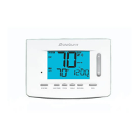
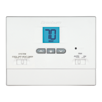
Outlines compatibility for Models 3000/3200 and their terminal designations.

Installation

Replacing Existing Thermostat

Step-by-step guide for removing and replacing an old thermostat.

Installing Your New Thermostat

Instructions for installing the thermostat in a new location and initial setup.

Testing Your New Thermostat

Pre-Testing Safety and Notes

Important safety warnings and notes before conducting thermostat tests.

Testing Heating, Cooling, and Fan

Procedures to test the heating, cooling, and fan functions of the thermostat.

Programming User Settings

Default Thermostat Settings

Lists the default operational settings after a reset.

Setting Temperature Differentials

Guides on adjusting first and second stage differentials for system response.

Temperature Adjustment

Adjusting Set Temperature

Instructions on how to review and change heating/cooling set points.

Additional Operation Features

Circulating Fan and Keypad Lockout

Explains fan operation modes and how to lock/unlock the keypad.

Compressor Protection and Low Battery

Details compressor protection features and low battery indicators.

Non-Volatile Memory and Status Indicators

Covers non-volatile memory and the meaning of various status indicators.

Understanding Status Indicators

Explains specific status indicators like COOL, EM HEAT, AUX, and CHECK.

Battery Replacement

Replacing the Batteries

Step-by-step guide for replacing the thermostat's AA batteries.

Troubleshooting

No System Operation and Compressor Delay

Addresses issues where the system won't turn on and compressor protection.

Setpoint Range and Fan Operation Issues

Troubleshoots setpoint limitations, continuous fan operation, and check indicators.

Wiring Diagrams

Wiring Diagrams for Model 3000

Provides wiring diagrams for Model 3000 conventional and heat pump systems.

Wiring Diagrams for Model 3200

Provides wiring diagrams for Model 3200 conventional and heat pump systems.

Limited Warranty Information

Warranty Facility and Contact Details

Specifies the warranty facility address and contact information for inquiries.
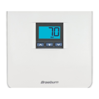
Related product manuals