EasyManua.ls Logo

Braeburn Builder 2200 User Manual

Braeburn Builder 2200
7 pages
To Next Page IconTo Next Page
Page #1 background imageLoading...
Page #1 background image
MODEL
2200
Builder Series
5-2 Day Programmable
Multi-Stage 2 Heat/1 Cool
Heat Pump Digital Thermostat
Compatible with low voltage multi stage
heat/cool systems with up to two stages of
heating and one stage of cooling. Do not use
this thermostat on applications with voltages
above 30 Volts AC.
© 2005 Braeburn Systems LLC • Patents Pending • All Rights Reserved. Pub. No. 2200-100-004
WARNING!
Important Safety Information
Always turn off power to the air conditioning or heating system prior to installing,
removing, cleaning or servicing thermostat.
• Read this manual thoroughly prior to installing, programming or operating
this thermostat.
This thermostat is designed for use with 24 Volt-AC low voltage multi-stage
heat pump systems.
• Do not use this thermostat on applications with voltages above 30 Volts AC.
This thermostat requires two (2) properly installed "AA" alkaline batteries to
maintain system clock during power outages.
• The system must have 24 Volt AC power present for proper system operation
and control.
Wiring must conform to all building codes and ordinances as required by local and
national code authorities having jurisdiction.
• Do not short (or jumper) across terminals at the heating or cooling system control
board to test the thermostat installation. This could damage the thermostat and
void the warranty.
• Do not select COOL mode of operation if the outside temperature is below 50˚ F
(10˚ C). This could possibly damage the controlled cooling system and may cause
personal injury.
This thermostat should only be used as described in this manual. Any other use is
not recommended and will void the warranty.
SPECIFICATIONS
1
1
• Electrical Rating: 24 Volt AC (18-30 Volt AC)
1 amp maximum load per terminal
3 amp total maximum load (all terminals)
• Control Range: 45˚ - 90˚ F (7˚ - 32˚ C)
Accuracy: +/- 1˚ F (+/- .5˚ C)
AC Power: 18-30 Volts AC
• DC Back-Up Power: 3.0 Volts DC (2 AA alkaline batteries included)
• Compatibility: Multi-stage heat pump systems with up to two stages of heating
and one stage of cooling.
Terminations: R, O, B, C, Y, E, G, W2
INSTALLATION
2
2.1
Replacing Existing Thermostat
1.
Always turn off power to the air conditioning or heating system prior to removing
existing thermostat.
2.
Remove the cover of your old thermostat and locate the wire terminals. Do not remove
wires from terminals yet.
3.
Using small pieces of masking tape, label wires prior to removal from terminals. Use
the chart below to determine the new terminal designations for your new thermostat.
Old Terminal from New Terminal for
Existing Thermostat New Thermostat Terminal Description
R, V-VR or VR-R R 24 VAC
B O Reversing Valve (Cooling)
O B Reversing Valve (Heating)
C C 24 VAC common
Y, Y1 or M Y 1st Stage Heat / Cool
W, E or W1 E Emergency Heat
G or F G Fan Control
W1, W2 or W-U W2 2nd Stage Heating
USER MANUAL
READ ALL INSTRUCTIONS BEFORE PROCEEDING
CONTENTS
SPECIFICATIONS
INSTALLATION
TESTING YOUR NEW THERMOSTAT
PROGRAMMING
ADDITIONAL OPERATION FEATURES
TROUBLESHOOTING
WIRING DIAGRAMS
1
2
3
4
5
6
7

Other manuals for Braeburn Builder 2200

Question and Answer IconNeed help?

Do you have a question about the Braeburn Builder 2200 and is the answer not in the manual?

Braeburn Builder 2200 Specifications

General IconGeneral
DisplayBacklit LCD
Stages of Heating1
Stages of Cooling1
ProgrammabilityNon-Programmable
Voltage24 VAC
Temperature Range45°F to 90°F (7°C to 32°C)
Power SourceBattery or Hardwired
TypeNon-Programmable Thermostat
CompatibilitySingle Stage Systems

Summary

Important Safety Information

Specifications

Installation

Replacing Existing Thermostat

Step-by-step guide to removing the old thermostat and preparing for the new one.

Installing Your New Thermostat

Instructions for mounting the new thermostat sub-base and connecting wires.

Testing Your New Thermostat

Programming

Default Thermostat Settings

Review the default operational settings and parameters after a reset.

Setting Current Time and Day

Configure the thermostat's internal clock and day of the week for accurate scheduling.

Thermostat User Options

Adjust user-configurable settings like temperature differentials and filter monitoring.

Setting Your Energy Saving Programs

Set personalized heating and cooling schedules to optimize energy efficiency.

Additional Operation Features

Review Set Temperature

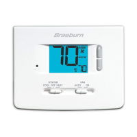
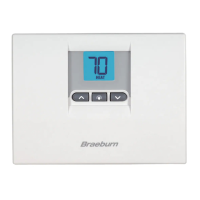
View the current setpoint temperature and understand temporary override options.

Temporary Program Override

Temporarily adjust the setpoint temperature, overriding the current program schedule.

Extended Hold (Vacation) Mode

Hold the current setpoint temperature indefinitely or for a specified duration.

Troubleshooting

Thermostat Does Not Turn On

Diagnose issues when the heating or cooling system does not start.

Incorrect Heating or Cooling

Address scenarios where the thermostat activates the wrong mode or stage.

Frequent System Cycling

Troubleshoot issues with the system turning on or off too often or not enough.

Thermostat Display Issues

Resolve blank displays, HI/LO indicators, or other display-related problems.

Troubleshooting (Continued)

Program Setpoint Issues

Check and correct program settings if the thermostat does not follow setpoints.

Temperature Extremes

Address issues with room temperature being too warm or too cold.

Fan Operation Issues

Diagnose fan running continuously or not at all.

Wiring Diagram

Related product manuals