3 Installer Guide
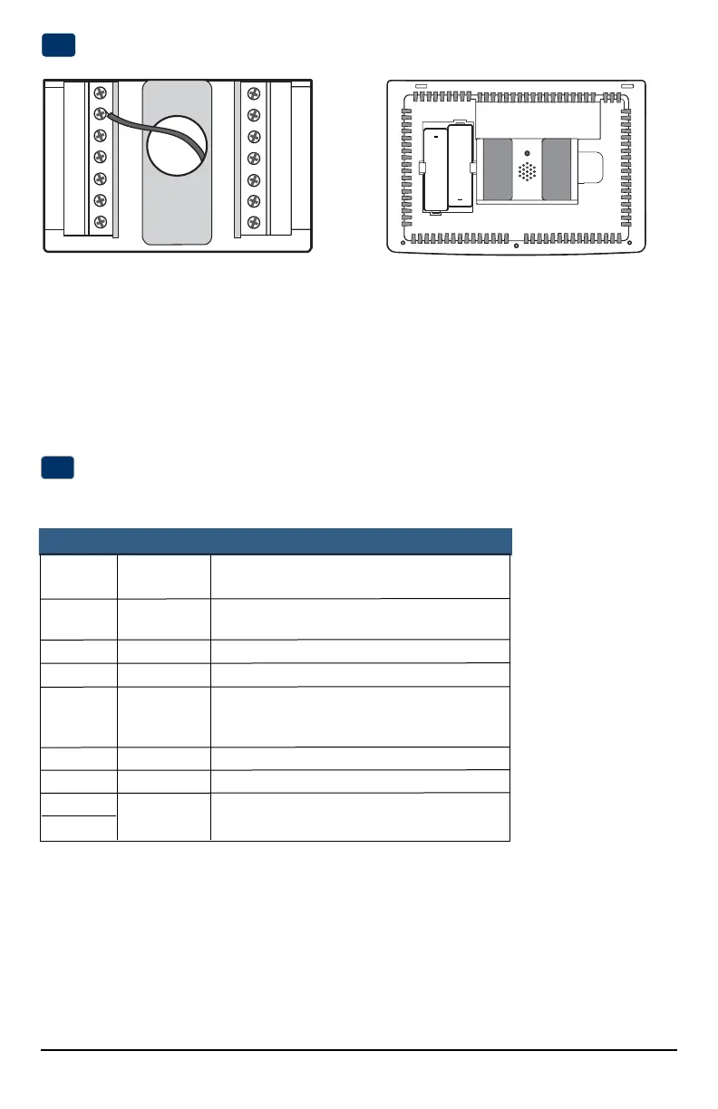
Provide Power
C
24VAC Power Terminal (C)
2
Wiring Terminations for model 5020
Terminal Function Description
Rc Input 24VoltACCoolingTransformer
(DualTransformerSystemsOnly)
Rh Input PowerConnection(24VoltACHeating
TransformerorMillivoltPowerSource)
G Output FanControl
W1 Output ConventionalHeatRelay
O/B/V3 Output (O)CoolActiveReversingValve
(B)HeatActiveReversingValve
(V3)ZoneValvePowerClose
Y1 Output CompressorRelay
C Input 24VoltACTransformerCommon
S1
S2
Connect Your Wires
3
Input OptionalRemoteSensor(indoororoutdoor)
+
+
• For24VoltACpower,youmustconnectthecommonsideofthetransformertotheCterminalonthethermostatsub-base.In
dualtransformerinstallations,thetransformercommonmustcomefromthecoolingtransformer.
• Forbatterypower,insertthe2supplied“AA”typealkalinebatteriesintothebatterycompartmentlocatedintherear
housingofthethermostat.MakesuretopositionthePositive(+)andNegative(-)sidesofthebatteriescorrectlywith
the+/-symbolsinthebatterycompartment.
Batteries Installed as Shown
 Loading...