Braemar Integrated Cooling
Effective from January 2011 V10 –
Updated 2
nd
April 2011
Page 7
“TH” Extra Air heaters are designed for use with an Integrated Cooling refrigerated cooling systems.
• These models include an “X” in their model numbers, eg, TH3X20, TH4X30 and TH5X32. The following
points must be taken into account to ensure correct operation of both the refrigerated cooler and the heater.
• Ensure that the refrigerated cooling unit is sized correctly to suit the house and the heater.
• The cooling coil (evaporator) should be installed 1.5 to 2.5 m from the heater supply air outlet.
• To prevent excessive air flow restriction, the ducting between the heater and the cooling coil should be as
straight as possible. If bends are required, use the largest bend radius possible.
• The thermistor must be located after the cooling coil 3m along the duct from the heater outlet, and fitted
centrally in the top of the duct.
• A correctly-sized low level return air grille with a filter MUST be fitted when installing Integrated Cooling
refrigerated cooling – refer table ON PAGE 9 as a guide:
NOTE:
The “A/C” terminals on the BSC circuit board in the heater supply 24Vac control voltage to operate the cooling
system. The connection from the “TH” heater is direct to the Terminals marked “1 & 2” on the Integrated Cooling
outdoor terminal strip. Refer Page 12.
Ensure that “COOL 2” is selected during system set-up to enable the system to operate the refrigerated cooling
system - refer to “Commissioning” section in these instructions.
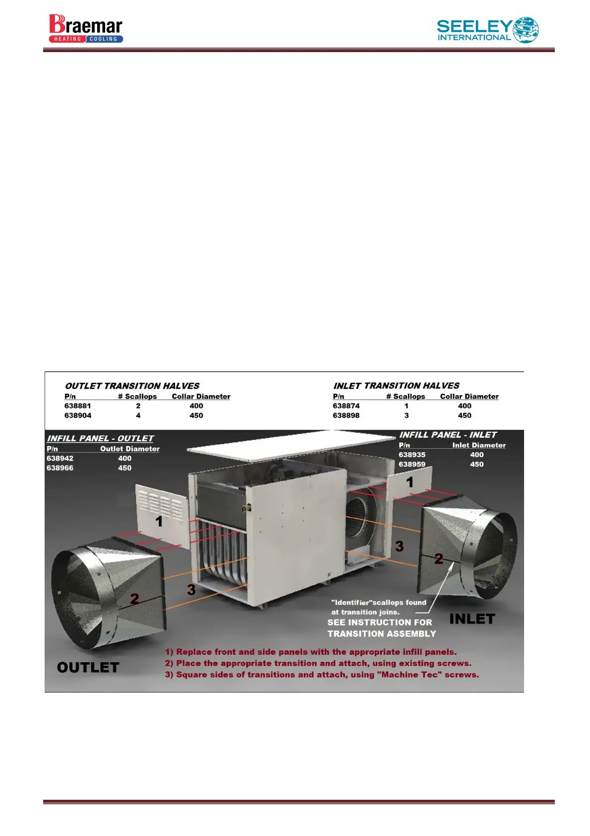
DUCT CONNECTIONS:
 Loading...