3997_r02 3/13
Ignitor:
- Peak ignition voltage: 15KV con carico di
30pF
on request:
12/18 KV
- Peak current: 800 mA
- Spark repetition rate: 25 Hz
on request:
1 ... 8/10/12/16 Hz
- Max. length of the cable: 2 m
- Spark gap recommended: 2-4 mm
- Consumption: 2.5 VA
- Spark energy: 20 mJ
Weight:
170 g
CONSTRUCTION
The enclosure made of plastic material and the varnishing
of the circuit board protect the control from mechanical
damages, dust and dirt from the conditions of installation.
Through the use of a board assembled with surface
mounted components and of a new patented circuit
generating the ignition spark which limits the EM to a
minimum, it has been possible to reduce the printed circuit
board dimensions and to realize even the most complex
executions with extremely compact dimensions.
A varistor protects the control from voltage transient on the
main supply, caused for example by discharges such as
thunderbolds. An internal fuse protects the relays of the
control box in case of short circuits on the outputs (valves,
fan and lockout signal). In any case the control must be
protected with a fast blow external fuse suitable to the load
connected and never exceeding 3.15 A.
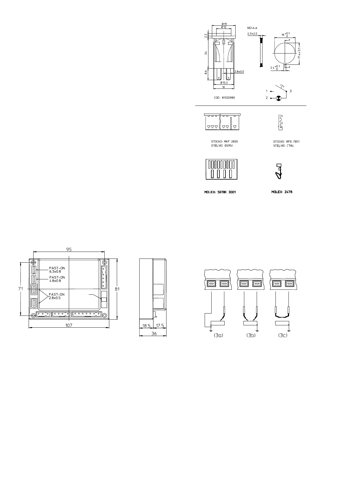
OVERALL DIMENSIONS
The control units of the MICROFLAT series can be
supplied in different executions but with the same
enclosure. The following figure (Fig. 1) shows the overall
dimensions of the controls.
CLIP TO
EXTRACT
THE INTERNAL
Fig. 1
POSSIBLE FIXING
top: self-tapping screw UNI 6951AB 2,9x22
M3x22 screw UNI6107
Screwplast self-
ISO0003 F
3.5x13
Screwplast self-
ISO0003 F
3.9x13
ACCESSORI
The control units are usually supplied with a kit of female
connectors and/or a reset button (see Fig.2 and Fig.3).
Do not fit terminals and female connectors of different
types.
RESET BUTTON
DRILLING PLAN
LOCK-OUT SIG.
Fig. 2
FEMALE CONNECTOR
TERMINALS
Fig. 3
CONNECTION
The use of non-reversible connectors with a different
number of poles makes the connection easy and reliable.
One-way fast-on connectors of different sizes for ignition
and detection electrodes permit their easy installation and
replacement.
The dual output ignition device allows spark generation on
one point (3a), two points (3b) or between two electrodes
isolated from the metal frame of the burner (3c), see Fig.4.
The configuration (3c) assures a limited EM emission.
Fig. 4
Provisions such as strain relieves, sufficient earth terminals
and neutral terminals should be present in the appliance or
in external connection boxes. With all types it is possible to
execute the connection with a J3 connector as shown in
Fig.5.
Types TM..F are prearranged for the connection of a safety
thermostat ST which stops the supply to the gas valve VG1
and causes a safety shutdown after a delay which is the
sum of waiting (pre-purge) and safety times.
 Loading...