4/13 3997_r02
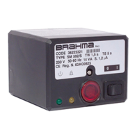
(4a) W ith safety thermostat (4b) Without safety therm ostat
Fig. 5
DIRECTIONS FOR USE
− For technical and safety reasons a regulation shutdown
must occur every 24 hours (systems for non-permanent
operation);
− automatic controls are safety devices and must not be
opened. The manufacturer’s responsibility and
guarantee are invalidated if the control is opened;
− the control must be connected and disconnected only
after switching off the main power;
− the control can be mounted in any position;
− avoid exposing the control unit to dripping water;
− ventilation and the lowest temperature ensures the
longest life of the control;
− make sure that the type (code and times) you are using
is correct before installing or replacing the control;
− the gas appliance on which the control is installed must
provide adequate protection against the risk of electrical
shock (at least IP20).
ELECTRICAL INSTALLATION
− The applicable national regulation and the European
standards (e.g. EN 60335-1/prEN 50165) regarding
electrical safety must be respected;
− live and neutral should be connected correctly, a
mistake could cause a dangerous situation, i.e. the
valves would still be live with the thermostats and limits
switched off. If live-neutral polarity is not respected the
control performs a non-volatile lockout at the end of the
safety time at starting up;
− before starting the system check the cables carefully.
Wrong connections can damage the control and
compromise the safety;
− the earth terminal of the control, the metal frame of the
burner and the earth on the main supply must be well
connected;
− avoid putting the detection cable close to power or
ignition cables;
− use a heat resistant cable for the detection probe, well
insulated to the ground and protected from possible
moisture (or water in general);
− use an ignition cable as short and straight as possible
and keep it far from other conductors to reduce the
emission of interference (max.length <2m and
insulation voltage >25KV).
In case of live-neutral network with unearthed neutral or
live-live network (with centre of the star not earthed) the
control can operate correctly by means of a built-in resistor.
In case of "partial" short circuits or bad insulation between
live and earth the voltage on the ionization probe can be
reduced until it causes the lockout of the control, because
of the impossibility of detecting the flame signal.
In the presence of this kind of network it is advisable to use
our step-up transformer type AR1.
CHECKING AT START
Always check the control before the first start and also after
any substitutions or a long period of non-operation of the
system. Before any ignition attempt make sure that the
combustion chamber is free from gas.
Then make sure that:
− if the starting attempt occurs without gas supply the
control performs a non-volatile lockout after TS;
− when stopping the gas flow while the control is in
running state the supply to the gas valve is interrupted
within 1 second, and after a recycling the control
proceeds to a non-volatile lockout;
− operating times and sequence are suitable;
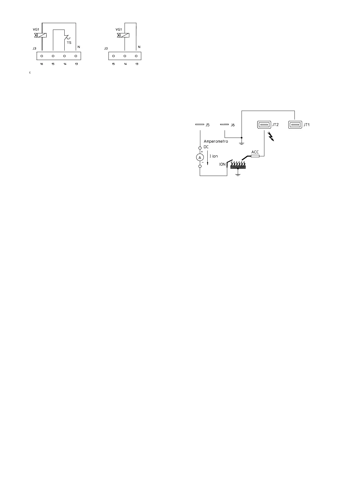
− the level of the flame signal is sufficient, see Fig.6 for
the measuring test;
− the ignition probe(s) is (are) adjusted in the most
stable way for a spark gap between 2-4 mm;
− the intervention of limiters or safety devices causes a
safety shutdown according to the application.
Fig. 6
OPERATION
At every start the control unit proceeds to a self-checking of
its own components. During the waiting or prepurge time
(TW) the operation of the flame signal amplifier is checked:
the internal circuit makes a test of the flame signal amplifier
circuit. A parasitic flame signal or a fault in the amplifier
prevent the control from starting.
In the types with fan control, before the elapsing of the
prepurge time, the air pressure switch contacts are
checked to prove their "no air flow" state.
Only if the test is positive the fan is started and with the air
pressure switch in "air flow" state the prepurge time begins.
At the end of the waiting or prepurge time the VG1 gas
valve is energized and the ignition device is operated. In
this way the safety time (TS) begins. If the presence of
flame is detected during the safety time the ignition device
is inhibited and, in the suitable models, the main valve
(VG2) is supplied or the independent auxiliary contact will
switch from off to flame detected position.
On the contrary, if the control detect no presence of flame
by the end of TS, it proceeds to non-volatile lockout, the
VG1 gas valve and the ignition device are switched off
while the lockout signal output is supplied.
Flame failure during the safety time causes the ignition
device to be activated within one second.
The attached diagrams are useful to understand how each
control operates.
NON-VOLATILE LOCKOUT - RESET OF THE CONTROL
When a control has gone to non-volatile lockout, a ten-
second delay should be allowed before attempting to reset
the control unit; if this time is not observed the control may
not reset correctly.
VOLATILE LOCKOUT – RESET OF THE CONTROL
The restart from the safety shut-down condition can only be
accomplished by an interruption of the main power and it
subsequent restoration.
This types of burner control units do not contain an
independent manual reset function. The application of
these types of controls is therefore restricted to only those
appliances where resetting by switching off the heat
demand is allowed by European standards.
 Loading...