14698_r00 11/18
WIRING DIAGRAMS
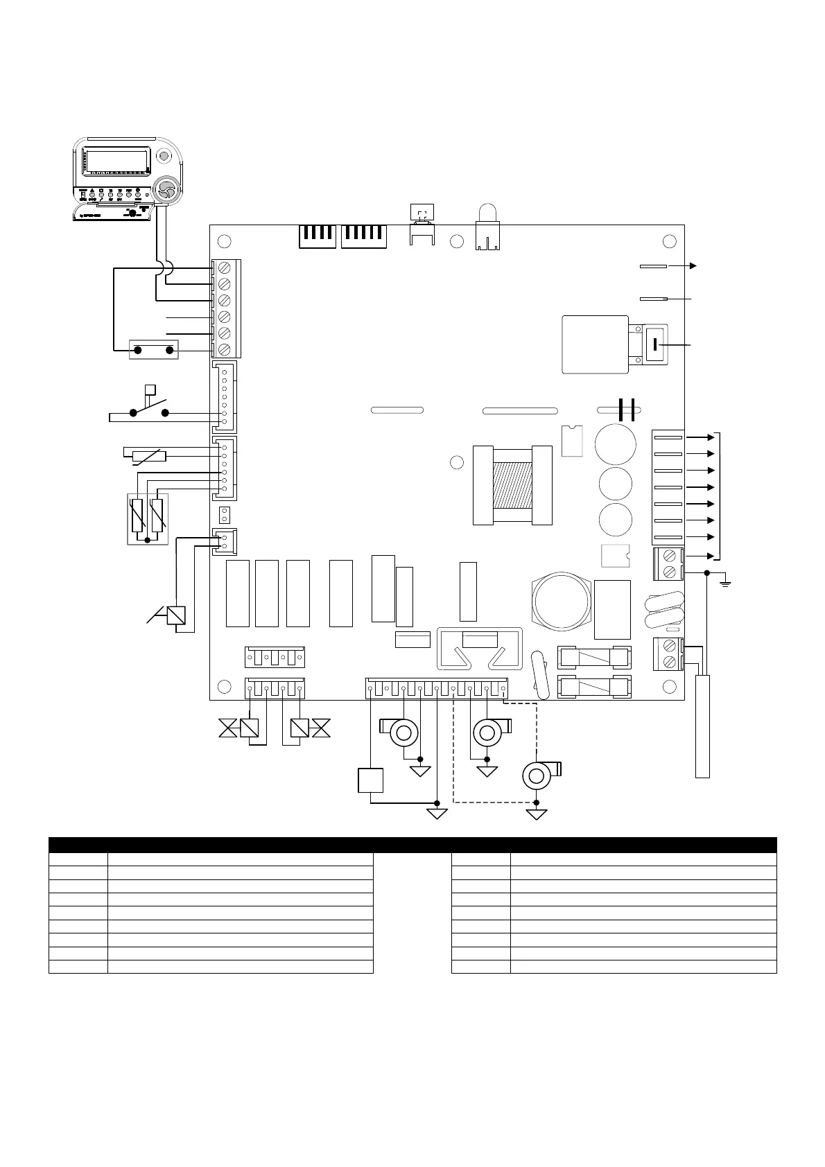
The following wiring diagrams refer to the most complete device versions.
WIRING DIAGRAM FOR BRAHMA DEVICES type TC340
A
.**.**.**
J12
J11
J10
JP1
J9
J8
J7
J6
J3
J5
J4
J2
RESET
J13 J14
MARRONE
NERO
BLU
2
4
3
2
1
4
3
2
1
5
4
3
2
1
5
6
1
2
3
4
5
6
7
1
2
3
4
5
6
1
1 2 3 4
1 2 3 4
1 2 3 4 5 6 7 8 9
2
1
2
1
PE
PE
Key to symbols
GA1 Chronothermostat type ENCRONO GA1 SR Heating circuit probe
EF Burner motor SA Room temperature probe (optional)
FAN Hot air blower APS Air pressure switch
FAN2 Second hot air blower STF Fire damper
ACC1 Remote auxiliary ignition transformer SL LED signalling
ACC2 Inbuilt ignition transformer RESET Reset push-button
EV1 First valve stage JP1 LPG/GAS selection jumper
EV2 Second valve stage EX Connection for cascade appliances
MOD Gas valve current modulator ION Ionization electrode