CEBORA S.p.A. 4
3.302.140 21/05/03
2 - SYSTEM DESCRIPTION
2.1 - Introduction.
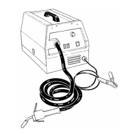
The BRAVO MIG110 is a system for MIG process welding of mild and stainless steel, and
aluminum. It is made up of an electric power source, art. 484, with incorporated torch and wire
feeder group.
2.2 - Technical specifications.
To verify the technical specifications, see the machine plate, Instruction Manual, and Sales
Catalogue.
2.3 - Description of power source art. 484.
Art. 484 is an electro mechanic direct current power source, consisting of a single-phase
transformer and a rectifier bridge.
Referring to the electrical diagram in par. 5.1, drawings 2.3.1, 4.1 and table 4.2, we can
identify the main blocks that make up the power source.
The main switch (A) (14) powers the power transformer (46), through selectors (B) (15),
which, commutating opportunely the primary winding sockets of the transformer (46), change
the secondary winding voltage, and so the power source output voltage.
In this way they adapt the welding current to the welding requirement.
The rectifier bridge (38) connected at the transformer (46) secondary winding, rectifies the
welding current, and at its output is connected the inductor (46), integrated in the same core of
the power transformer, for the welding current leveling.
The control board (41), manages the power source output voltage by means the output
contactor (50), which is activated by the relay on the control board (41), driven by the torch start
button.
The wire feeder motor (40) supply voltage is picked-up from the rectifier (38) output, so that
is subjected at the variations imposed by selectors (15) setup, and at the voltage difference due to
loaded or no loaded transformer (46) working conditions. More exactly, at the increasing of the
power source output voltage corresponds automatically an increase of motor (40) speed. The
wire speed fine adjustment is performing by the control board (41) electronic regulator, through
proper potentiometer (knob D).
Output welding current and wire speed must be adapted, to the welding requirements,
manually by the operator.
The thermostat (47) is locates on the power transformer (46) secondary winding, and its
intervention interrupts the power source supply.
2.3.1 - Power source commands and signals.
M12179B, MB120A, WFW12179, 117-092, 83-363 (Mig 110)