The Bray/VAAS Unidirectional Series Knife Gate Valve (940/950/952/980/985 Series) is a flow control device designed for repeatable unidirectional shutoff in various industrial applications. This operation and maintenance manual provides essential information for the safe and effective installation, commissioning, operation, and maintenance of these valves.
Function Description:
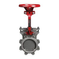
The Bray/VAAS Unidirectional Series Knife Gate Valve is engineered to provide reliable shutoff in systems where flow is primarily in one direction. Its design features a rugged, single-piece cast body and offers both metal and soft seating options to accommodate a wide range of unidirectional sealing requirements across diverse industries. The valve's primary function is to control the flow of media by allowing or preventing its passage through a pipeline. The knife gate design is particularly effective in handling slurries, viscous fluids, and media containing solids, as the gate can cut through the material to achieve a tight seal. Flow direction is indicated on the valve body, and proper orientation is crucial for optimal performance. The seat side of the valve is marked with "SEAT" on the body and on the gate top side to ensure correct installation.
Important Technical Specifications:
The manual outlines several key technical aspects of the valve:
- Series: 940/950/952/980/985 Series.
- Seating: Available with both metal and soft seating options, catering to different application needs and media types.
- Body Construction: Features a rugged, single-piece cast body for durability and reliable performance.
- Actuation: Can be operated manually (via a handwheel) or by a cylinder (pneumatic actuator).
- Air Pressure (for cylinder-operated valves): Recommended air pressure for cylinder-operated valves is 80-120 psi (5-8 bar). The supply air must be instrument quality, filtered, and free from moisture, dirt, and other foreign particles.
- Electrical Accessories: Valves can be supplied with electrical accessories such as limit switches and solenoid valves, requiring adherence to local electrical safety codes and regulations for proper wiring and power supply.
- Material Specification: Valve size and brief material specifications (e.g., "SS" for stainless steel or "DI" for ductile iron) are marked on the valve body. A stainless steel nameplate on the yoke provides comprehensive information, including the Bray/VAAS work order number and unique serial number, which are essential for service and spare parts inquiries.
- Packing Details: The manual provides a detailed table for packing sizes (Sq. 8, Sq. 10, Sq. 12.7, Sq. 16, Sq. 19 mm), corresponding lengths (180 mm to 2035 mm), and quantities (3 to 5 rings) for various valve sizes (2 inches to 36 inches).
Usage Features:
- Unidirectional Flow: Designed specifically for applications with flow in one direction, with clear markings on the valve body for correct orientation.
- Versatile Installation: Can be installed in various orientations, though for horizontal lines with potential for solids settling, installing the valve with the stem above horizontal/inclined/vertical is preferable.
- Flange Mounting: Installed between flanges using fasteners and gaskets.
- Blind Tapped Holes: Bolt holes in the chest area are blind tapped, requiring care to avoid bottoming out bolts during tightening. Studs and nuts are recommended for chest area bolts if correct size bolts are unavailable.
- Support for Larger Valves: Valves 8 inches and over installed in vertical pipes require support to prevent improper operation or failure.
- Cylinder-Operated Valves: Require instrument quality, filtered air supply. Initial operation involves cycling the valve 2-3 times after connecting air and electrical supplies.
- Manual Valves: Operated by a handwheel, requiring manual opening and closing to observe valve operation.
Maintenance Features:
- Gland Packing Adjustment: Gland packing is pre-tightened at the factory but may require adjustment on-site due to transit loosening. Leakage checks after pressurization and uniform tightening of gland nuts in a criss-cross pattern are recommended. Over-tightening should be avoided to prevent excessive friction and packing damage.
- Lubrication:
- Manual Valve Stem: Requires regular lubrication via a nipple on the collar for smooth operation.
- Cylinder-Operated Valves: Do not require routine lubrication. However, if the cylinder actuator is disassembled for repair, the cylinder wall and seals must be lubricated with a lithium-based grease prior to reassembly.
- Packing Replacement: A detailed procedure is provided for replacing packing for both manual and cylinder-operated valves. This involves relieving line pressure, fully closing the valve, ensuring the line is empty, disconnecting the stem from the gate, removing gland nuts and gland, prying out old packing layers, cleaning/replacing wiper rings, inserting new packing layers one at a time (staggering cut ends), and reassembling.
- Seat Replacement: A step-by-step guide for replacing the valve seat is included. This process requires relieving line pressure, closing and flushing the valve, removing it from the line, clamping it vertically, disconnecting the stem, tilting the superstructure, removing the old seat, inserting the new seat, and reassembling.
- Actuator Maintenance: The Bray/VAAS pneumatic cylinder actuator is designed for low maintenance, featuring an FRP tube lubricated for life with a special coating. It requires filtered, dry, instrument quality air.
- Spare Parts: Recommended spare parts include gland packing, a spare seat, and a cylinder repair kit. The valve serial number and work order number from the nameplate are crucial for ordering correct parts.
- Troubleshooting Guide: A comprehensive table identifies common issues (e.g., media oozing, valve leaks, high torque, valve jerks, inability to close/open) along with their possible causes and corresponding solutions. For instance, media oozing from gland packing indicates deteriorated packing, requiring replacement. Valve leaks in a closed position could be due to a worn or torn seat or a scratched gate, necessitating replacement of the respective component. High torque during seating/unseating points to misalignment between the gate and stem or improperly tightened packing, requiring adjustment or tightening. Valve jerks can be caused by insufficient air supply or dust accumulation in the solenoid valve, requiring increased pressure or cleaning. An inability to close or open the gate might indicate a bent gate or incorrect valve orientation.
Safety Instructions:
The manual emphasizes critical safety instructions, including:
- Qualified Personnel: All installation, commissioning, operation, and repair must be performed by qualified personnel familiar with the device and possessing appropriate qualifications (e.g., training in electrical equipment, PPE, first aid, and hazardous locations if applicable).
- Hazard-Free Use: Users must observe all notes and warnings to maintain a safe condition and ensure hazard-free operation.
- Damage Prevention: Precautions must be taken to prevent damage from rough handling, impact, or improper storage. Abrasive compounds or sharp objects should not be used for cleaning.
- System Safeguards: Control systems must have proper safeguards to prevent injury or equipment damage in case of component failure.
- Line Pressure Relief: Line pressure must be relieved before loosening gland nuts or attempting any maintenance to avoid injury or equipment damage.
- Electrical/Pneumatic Disconnection: For valves with pneumatic actuators or electrical accessories, electrical and pneumatic supplies must be disconnected before maintenance.
- Storage: For long-term storage, the valve should be wrapped with a polyethylene cover, ports covered with plastic caps, and stored indoors in a vertical position in a cool, clean area to prevent packing damage. The gate should be off the seat to prevent compression set.
- Unauthorized Modifications: Any modification or use of unauthorized parts voids all warranty considerations.