4 of 52© 2021 BRAY INTERNATIONAL, INC. ALL RIGHTS RESERVED. BRAY.COM EN_TSM-2004-6A Advanced_Set-Up_20211012
SERIES 6A
ADVANCED SETUP GUIDE
-
+
1
10
138
238
9
$$
$
$
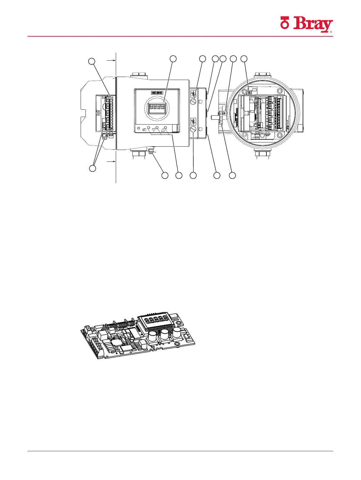
① Display ⑧ Output: Actuating pressure Y2
1)
② Restrictor Y1 ⑨ Restrictor Y2
1)
③ Output: Actuating pressure Y1 ⑩ Buttons
④ Input: Supply pressure PZ ⑪ Ground terminal
⑤ Safety catch ⑫ Connecting terminals of option modules
⑥ Transmission ratio selector
2)
⑬ Connecting terminals of basic electronics
⑦ Friction clutch adjustment wheel
1) for double-acting actuators
2) visible when the positioner is open
Figure 2 View of positioner in f ameproof enclosure, cover opened
3.3.2 Basic electronics
Figure 3 Basic electronics, schematic representation
The basic electronics contains:
• CPU
• Memory
• Analog-to-digital converter
• Display
Description
3.3 Device components
SIPART PS2 with 4 to 20 mA/HART
Operating Instructions, 10/2020, A5E00074631-AF 29

 Loading...

