5
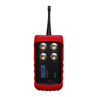
(2.2) RX-101 Receiver
Using the cabling as supplied, each RX-101 Receiver should be mounted vertically and
within 10ft of the power and release connections of the trap.
To lengthen the power/release cabling use a connector that is rated for outdoor use and
meets current electrical standards. Ideally the Receiver antenna should have an
unobstructed line of sight to the Transmitter antenna.
To make the Receiver connections to your traps, use the appropriate plug for the trap.
These parts can be purchased from your trap manufacturer or dealer. Release plug and
socket wiring diagrams for your trap can be obtained from your trap manufacturer or
dealer.
Receiver Connections – 1Trap Receiver
Power From Trap
10ft long 4 core cable = Receiver power and trap release connections.
Red= 12V +ve.
Black= 12V –ve.
White and Green = trap release connections. Orientation of the white and green wires is
not important.
Power From 120Vac Wall Outlet
10ft 120V ac power cord = Receiver power.
Plug into GFCI protected 120V outlet.
10ft 2 core cable = trap release connections.
Orientation of the wires is not important.
Receiver Connections – 2 Trap Receiver
Power From Trap
10ft 4 core cable = Receiver power and trap release connections.
Red= 12V +ve.
Black= 12V –ve.
White and Green = trap release connections Trap A. Orientation of the white and green
wires is not important.
2 pin socket and plug = trap release connections Trap B. Orientation of white and green
wires is not important.
Make solder connection of customer supplied cable into plug from Trap B.