7
(3) Set Up
(3.1) Counter Unit Set Up
The Counter identity and operation are set via the three 8 position dipswitches.
To access the dip switches carefully remove the cover so as not to pull the internal wiring
that links between the cover and the enclosure body.
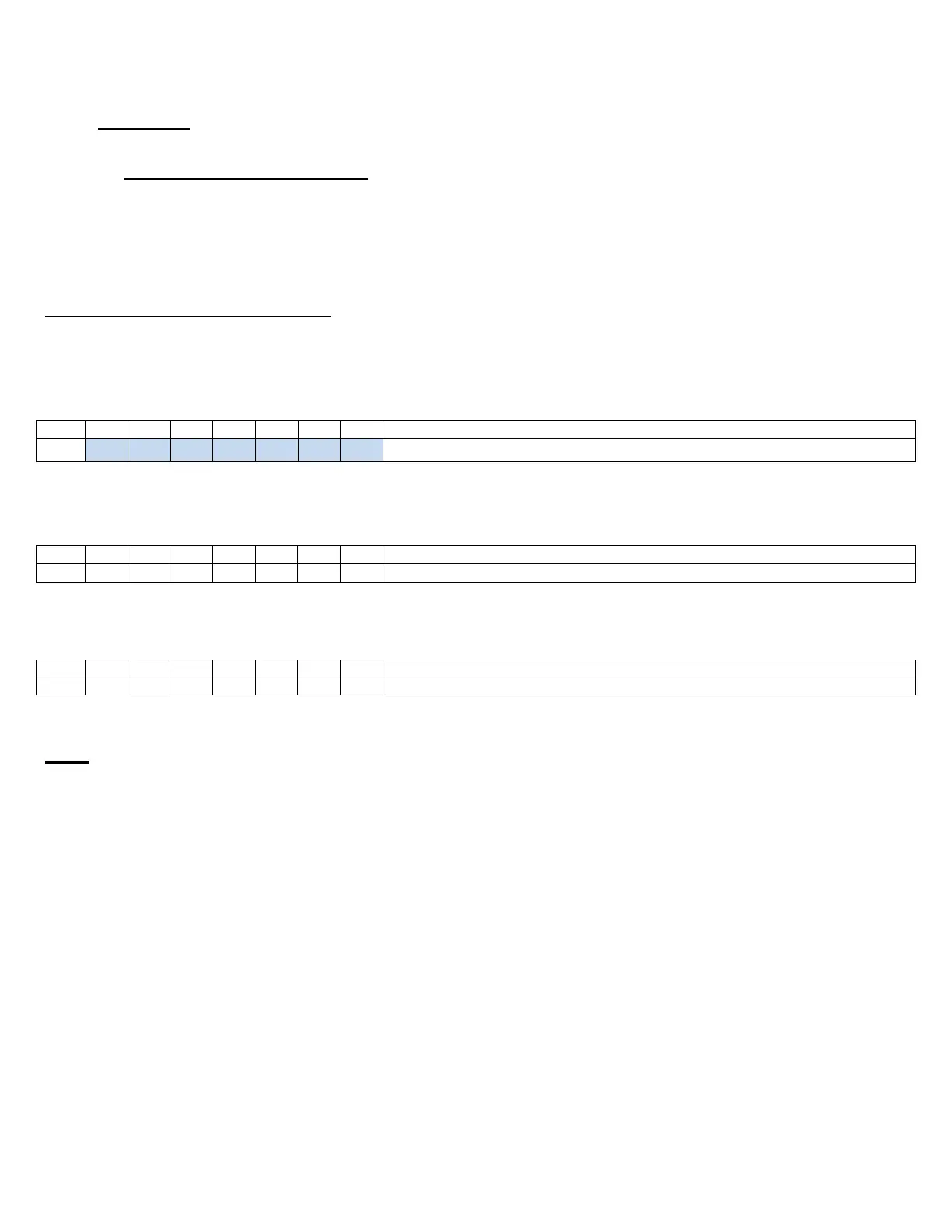
Counter Dipswitch Settings
Switch numbers are printed on the body of the dipswitch.
TOP
The (7) CHN switches must match between TX,RX and Counter – Used to set RF frequency
MIDDLE
BOTTOM
CHN Channel Dipswitches
The CHN dipswitch settings on the Receiver, Transmitter and Counter must match for the
system to operate.
These will be preset when the unit is shipped and so under most circumstances
should not need you to change them.
The CHN dipswitches (switches 2-8 of the top dipswitch) are the primary method of
Transmitter identification. They set the frequency of the Transmission signal and give 128
possible frequency variations. Using these settings for identification eliminates cross calls
between adjacent fields because each field can have a different working frequency.