118
8
8
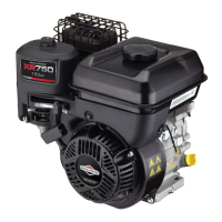
NOTE: Do not apply force to the wire gauge! The
disc valve is retained by an internal bracket
which will be distorted if pressure is applied to
disc.
Figure 4
Install Breather
1. Place new gasket and breather assembly
on cylinder. Torque to screws to values
listed in Section 12 - Engine
Specifications.
2. Securely insert breather tube into breather
assembly.
Service Breather - Vertical Models
210000, 280000, 310000, 330000
Current Production
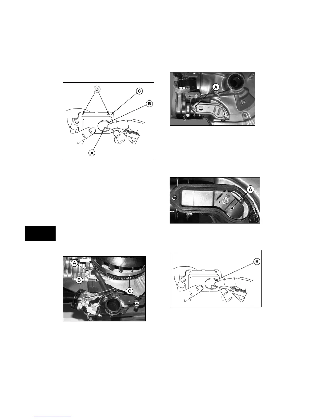
Remove Breather
1. Remove breather tube (B, Figure 5) from
breather cover (A).
Figure 5
2. Remove two screws (B, Figure 6),
breather cover. Discard gasket (before
date code 070719xx) or clean off sealant
(after date code 070718xx).
Figure 6
Check Breather
1. Remove and check breather reed
(A, Figure 7). If the reed is worn or bent, it
cannot function properly and must be
replaced.
Figure 7
2. Inspect the oil drain-back hole
(B, Figure 8). Insert a fine wire to ensure
the opening is not plugged.
Figure 8
 Loading...