Do you have a question about the Briggs & Stratton VANGUARD 810 EFI and is the answer not in the manual?
Explains what DTCs are, how they are set, stored, and their impact on engine operation.
Provides critical precautions to prevent damage to the ECM during service.
Lists DTCs, their descriptions, and corresponding engine components.
Troubleshooting procedures for P0031 and P0032 DTCs related to the O2 sensor heater.
Troubleshooting procedures for P0107 and P0108 DTCs related to the MAP sensor.
Comprehensive electrical schematic for Model 490000 EFI system.
Comprehensive electrical schematic for Models 540000/610000 Turf EFI.
Comprehensive electrical schematic for Model 610000 Marine EFI system.
Troubleshooting steps for when the engine fails to crank.
Troubleshooting steps for when the engine cranks but does not start.
Essential safety measures to follow before working on the fuel system.
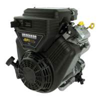
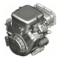
| Displacement | 810 cc |
|---|---|
| Fuel System | Electronic Fuel Injection (EFI) |
| Cooling System | Air-cooled |
| Starting System | Electric Start |
| Gross Horsepower (HP) | 27 HP |
| Compression Ratio | 9.0:1 |
| Horsepower | 27 HP |
| Governed Speed | 3600 RPM |
| Starter | 12V Electric |
| Engine Type | V-twin |
| Lubrication | Full Pressure |
| Oil Capacity | 2.0 qt |
| Ignition System | Electronic |
| Battery Requirements | 12V |
| Spark Plug Gap | 0.030 inches (0.76 mm) |
| Valve Clearance (Exhaust) | 0.007 in |






 Loading...