Do you have a question about the Briggs & Stratton Vanguard EFI 380000 and is the answer not in the manual?
Steps for verifying the engine's on-board diagnostic system status.
Explanation of how the ECM uses sensor signals to detect faults.
Function of the MIL as a diagnostic indicator for current faults.
Location and purpose of the DLC for ECM communication.
Steps for connecting the power supply harness for diagnostics.
Method to read DTCs using the Malfunction Indicator Lamp.
Using scan tools to read and clear Diagnostic Trouble Codes.
Using the diagnostic tool for reading and clearing DTCs.
Techniques for safely probing connector terminals for testing.
Precautions to prevent damage to the ECM from voltage spikes.
Troubleshooting codes related to the Manifold Absolute Pressure sensor.
Troubleshooting codes for the Manifold Air Temperature sensor.
Troubleshooting codes for the Engine Head Temperature sensor.
Troubleshooting codes for the fuel injector circuit.
Troubleshooting codes for ignition coil circuits.
Detailed pin assignments for the Engine Control Module connector.
Overall wiring diagram for the EFI system.
General overview of engine symptoms and diagnostic approach.
Diagnostic steps for an engine that does not turn over.
Troubleshooting steps for an engine that cranks but won't start.
Diagnosis for reduced engine power.
Troubleshooting engine speed fluctuations.
Procedure to safely check and relieve fuel system pressure.
Overview of fuel system parts and their removal/installation.
Steps for removing and installing the Engine Control Module.
Steps for removing and installing the fuel pump module.
Steps for removing and installing the throttle actuator motor.
Procedures for removing and installing the EFI wire harness.
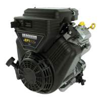
| Fuel System | Electronic Fuel Injection (EFI) |
|---|---|
| Cooling System | Air-cooled |
| Starting System | Electric Start |
| Fuel Type | Gasoline |
| Engine Type | V-Twin |
| Displacement | 627 cc |
| Power Output | 18.0 HP |
| Lubrication | Full Pressure with Oil Filter |