fig. 5).
14. Enlarge holes B in the boot to approx. 18 mm.
15. Place the backplates and the spacer tubes over the bolts and posi-
tion the assembly in the just drilled holes.
16. Position the two strips D on the inside of the chassis.
17. Attach the tow bar at points B and C.
18. Tighten all nuts and bolts to the torque indicated in the table.
19. Fit the rearmost exhaust silencers and heat shields.
20. Reshape the heat shields to ensure they cannot touch the tow bar
and exhaust.
21. Fit the bumper along with the tempex spacer.
22. Fit the ball housing, including socket plate, flat washers and self-loc-
king nuts.
23. Tighten all nuts and bolts to the torque indicated in the table.
24. Fit the rear lights.
25. Replace the items removed in step 1.
For dismantling and fitting the vehicle parts, see the site handbook.
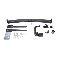
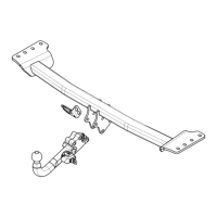
For fitting instructions and attachment method, see drawing.
See the assembly manual supplied for instructions on fitting the remova-
ble ball system.
MONTAGEANLEITUNG:
1. Den Fußboden im Kofferraum frei machen.
2. Die Rücklichter demontieren. (Siehe Abbildung 1).
3. Stoßstange einschließlich Styropor-Füllteil demontieren. (Siehe
Abbildung 1).
4. Den angegebenen Teil mit Hilfe der Schablone aus der Stoßstange
herausschneiden. (Schablone außen auf der Stoßstange anlegen)
5. Gemäß Abb. 2 das angegebene Teil herausschneiden.
6. Die hintersten Stoßdämpfer und Hitzeschilder demontieren.
7. Gemäß Abb. 3 die angegebenen Teile abschneiden.
8. Den stählernen Stoßbalken abmontieren.
9. Die Löcher A etwa 13 mm durchbohren. (Siehe Abbildung 4).
10. Den stählernen Stoßbalken wieder einsetzen.
11. Die Anhängervorrichtung bei den Punkten A montieren und in der
Mitte ausrichten. (Zie fig. 5).
12. Die Löcher B etwa 11 mm durchbohren. (Siehe Abbildung 5).
13. Die Löcher C etwa 11 mm auf der Unterseite des Fahrgestells boh-
ren. (Siehe Abbildung 5).
14. Die Löcher B im Kofferraum bis auf etwa 18 mm vergrößern.
15. Die Gegenplatten und Distanzhülsen über den Schrauben anlegen
und das Ganze in die soeben gebohrten Löcher einsetzen.
16. Im Langsträger die beiden Streifen D anlegen. .
17. Die Anhängervorrichtung bei den Punkten B und C anbringen.
18. Alle Schrauben und Muttern gemäß den Angaben in der Tabelle
festdrehen.
19. Die hintersten Stoßdämpfer und Hitzeschilder montieren.
20. Die Hitzeschilder so formen, dass sie die Anhängervorrichtung und
den Auspuff nicht berühren können.
21. Stoßstange einschließlich Styropor-Füllteil montieren.
22. Das Kugelgehäuse einschließlich Steckdosenplatte,
Unterlegscheiben und selbstsichernder Muttern montieren.
© 476770/14-07-08/4
D
NOTE:
* Should this installation process entail the cutting of the bumper – con-
formation MUST
be obtained by the installation engineer of the custo-
mer’s acceptance prior to completion. Brink International do not accept
responsibility for any matters arising as a result of this miscommunica-
tion.
* The dealer should be consulted for possible necessary adjustment(s)
"of the vehicle".
* Remove the insulating material from the contact area of the fitting
points.
* Consult your dealer for the maximum tolerated pull weight and ball
hitch pressure of your vehicle.
* Do not drill through electrical-, brake- or fuellines.
* Remove (if present) the plastic caps from the spot welding nuts.
* This fitting instruction has to be enclosed in the vehicle documents after
fitting the towbar.
 Loading...