==================================================================================================
x2
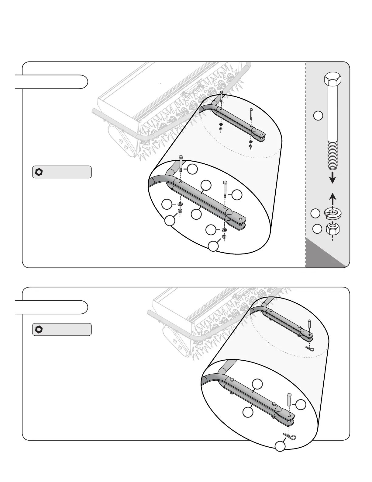
Assembly Step 3-A
Assembly Step 3-B
Hardware Panel 3
1. Align the tow bars.
2. From above, insert both
5/16 x 3” Hex Bolts (37)
from Hardware Panel 3, as
illustrated.
3. Beneath the tow bars, tightly
secure each bolt in place with one
5/16” lock washer (44) and 5/16” hex
nut (40).
1. At the end of the tow
bars (20), from above, insert
the Drawbar Pin (50).
2. Secure the pin with a Hairpin Cotter (51).
NOTE: For initial use, you may need to tap
or push the hairpin cotter into place by
applying some pressure with a tool.
37
40
44
Hardware Panel 3
20
20
20
20
37
50
37
44
44
40
40
51
ASSEMBLY
English Manual 9 L-1711BH-F
 Loading...