Belt Tension Adjustment
CAUTION: Disconnect all electrical power to the cooler
and insure that belt is not rotating before adjusting belt
tension.
Correct belt tension and alignment is
important, proper setup reduces power
consumption and prolongs life of belt and
motor. Check belt tension by squeezing belt.
Proper tension will allow deflection of ½ to ¾
inch. To increase or decrease belt tension,
loosen bolt in slot of motor support bracket.
Adjust belt to proper tension and retighten bolt.
CAUTION: Never operate unit with
pad frame(s) and/or air outlet grille
removed. This will result in an
overloaded condition and may
damage the motor.
Mounting Using Chain Kit
See
illustration (Fig. 2) for a typical installation. Remember, the framing
around the window must be strong enough to support the weight of the
cooler (approximately 250 pounds).
Chain Kit contains:
2 - Screw Hooks 2 - “S” Hooks
2 - Leg Leveling Bolts 2 - Rubber Pads
4 - 3/8” Square Nuts 4 - 3/8” Washers
2 - Hanger Straps 2 - #10-24 x 1/2” long Bolts
2 - #10-24 Nuts 2 - 5 ‘ Long Chain
Install chain kit as follows:
Attach screw hooks to outside window frame approximately two
feet above top of cooler. Be sure hooks are inserted to full depth in
window framing for maximum strength.
Attach chain to each hook.
Attach hanging straps to top of rear corner support legs in the 3/16”
diameter holes using the #10-24 bolts and nuts provided. Install
“S” hooks in straps.
Place leg leveling bolts through 7/16” diameter holes in bottom of
front corner support legs. Use nut and washer on outside of
cabinet and install rubber pads on outside ends of leveling bolts.
Place second nut and washer on leveling bolts inside cabinet.
Position the cooler so that the duct rests on the window sill and the
grille flanges are inside the window frame, allowing the “Z” shaped
bracket, located under the grille, to rest on the window sill and butt
against inside of window sill flange. Connect “S” hooks and screw
hooks to chain links that bring the cooler closest to a level position.
Use leg leveling bolts to brace the cooler away from the wall.
Adjust bolts and chain to level cooler. NOTE: Cooler may need to
be re-leveled to compensate for the added weight of water.
Tighten nuts on leveling bolts inside cabinet.
Lower the window to rest on the top of the duct (vertically hung
windows) or slide window closed against side of duct (horizontal
slider windows). Block any remaining unused portion of the
window opening with a suitable blocking material (Plexiglas, solid
plastic sheet, solid wood panel, etc.). It will be necessary to seal
any joints around the duct to prevent entry of rain, dust/dirt,
insects, etc. Any good quality caulking or foam tape will work.
An alternate installation method involves locating the unit in a suitable
window and using the included chain mounting kit to support the
weight of the cooler. As with platform or stand mounting, every
installation will be different. The exact requirements to mount and seal
a cooler against the weather will be best determined by the location
and at the time of the installation. Most installations will require
blocking of the unused portion of the window around the duct, or other
modifications to the window frame may be necessary.
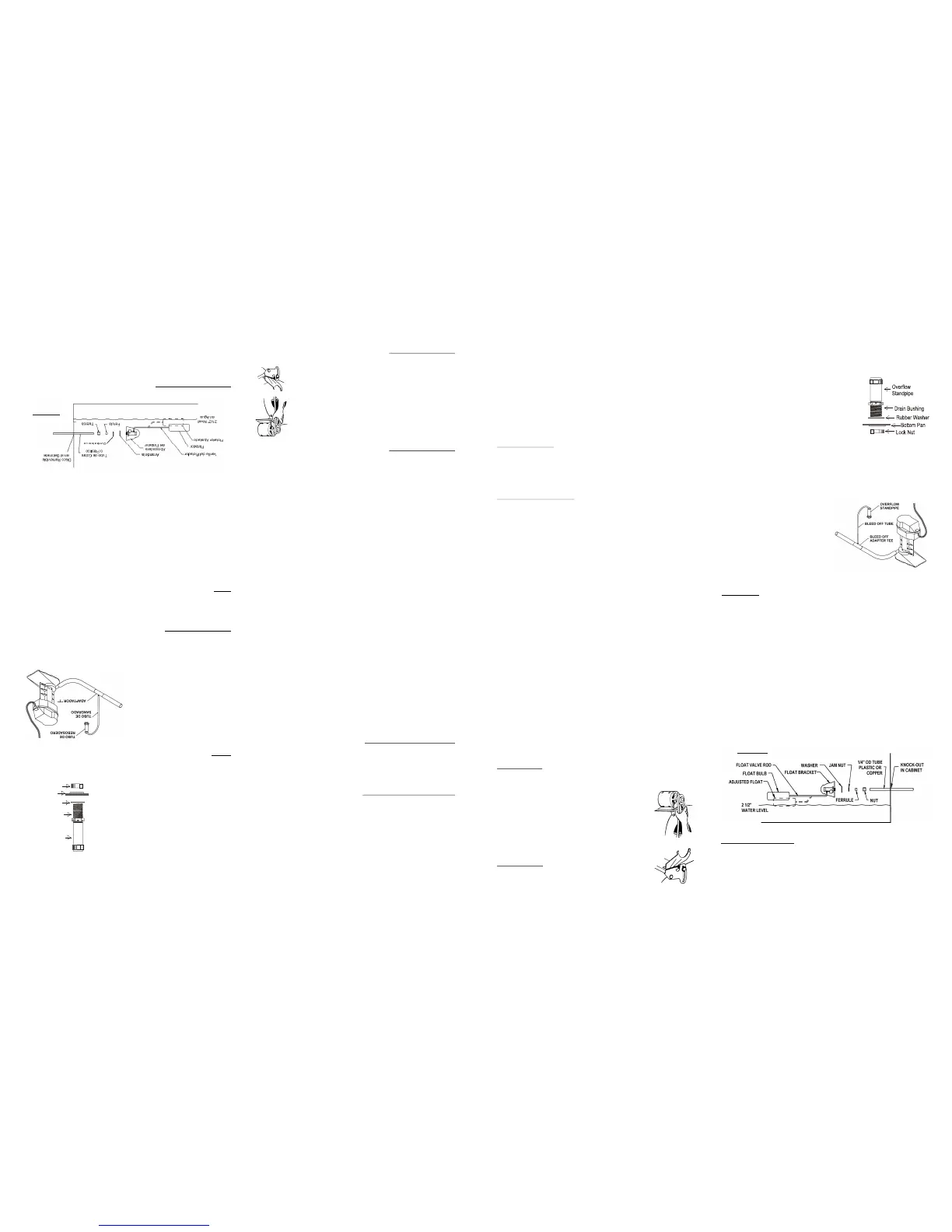
Install Overflow Standpipe / Drain Line
Install overflow drain bushing in bottom of cooler as follows:
Slide rubber washer over drain bushing.
Push drain bushing through bottom of
cooler, assemble and tighten lock nut.
Screw plastic overflow standpipe into
the drain bushing and tighten snugly
(hand tight) to prevent leakage.
Connect a suitable drain line (copper /
PVC / garden hose) to drain bushing.
Never drain water onto a roof; mineral
build-up or damage to roof may occur.
NOTE: Drain water in accordance with local plumbing codes.
Install Bleed-off
To minimize mineral scale “build-
up”use the included bleed-off
assembly. Remove the cap from
the bleed-off tee; insert the black
tubing and route the tubing
through standpipe opening into
the drain line To prevent
siphoning of the water, make sure
t at the bleed-off tee is above the
water level.
Connect Water Supply
CAUTION: All plumbing installations must comply with
local building and safety codes, and must be performed by
qualified personnel only.
NOTE: Coolers should not be connected to “soft” water systems. Soft
water will accelerate corrosion and decrease the effective life of pads
and cooler cabinet. Connect water line as follows:
A water supply valve should be installed at a convenient location
to allow the water supply to be turned on and off for servicing or
winterizing. Minimum 1/4“ diameter tubing should be used to
provide water to the cooler. Larger tubing is recommended if the
distance from the valve to the cooler is greater than 100 feet, then
reduced to 1/4” at the unit.
Install float valve in the bracket provided.
Connect tubing from water supply to float valve. Place
compression nut and ferrule over end of tubing, insert tube into
float valve then tighten compression nut to secure.
.
h
Brisa Evaporative Window Cooler - Use and Care Manual 3
Figure 3
OPERATION
Controls
The rocker control switches are used to select the operating mode of
the cooler. These switches control fan speed (High/Off/Low) and the
cooling (pump) operation (On/Off).
Ajuste de banda
PRECAUCION: Desconecte toda la corriente eléctrica
hacia el enfriador y asegúrese que la banda no este dando
vueltas antes de ajustar la tensión.
Tensión de la banda y alineación correcta es importante,
propia instalación reduce consumo de energía y
extiende la vida de la banda y la del motor.
PRECAUCION: Nunca opere la unidad sin los filtro(s)
y/o la rejilla de aire. Esto resultaría en condición de
sobrecarga y podría dañar el motor.
Revise la
tensión de la banda apretándola. Una tensión apropiada
permitirá una deflexión de ½ a ¾ de pulgada. Para
aumentar o reducir la tensión de la banda, afloje el
tornillo en la ranura de la montadura del motor. Ajuste la
banda a una tensión apropiada y apriete el tornillo.
Brisa Enfriador Evaporativo de Ventana - Maunal de Uso y Cuidado 3
Buje de Drenaje
Arandela de hule
Fondo
Tuerca
Tubo de
Rebosadero
Instale buje de drenaje y rebosadero
Instale el buje de rebosadero en el fondo del enfriador:
Deslice la arandela de hule en el buje.
Inserte el buje en el agujero del fondo, y
apriete la tuerca.
Atornille el tubo de rebosadero de plástico
al buje y apriételo ligeramente (apretado
con la mano) para prevenir fugas.
Conecte a una línea adecuada de drenaje
(cobre / PVC / manguera de jardín) al buje
de drenaje. Nunca drene el agua en el
techo; minerales se acumulan o daños al
techo pueden ocurrir.
NOTA:
Drene el agua de acuerdo con los códigos locales de plomería.
Instale el sangrado
Para minimizar la “acumulación de
sarro” use la ensambladura de
sangría incluida. Remueva el
tapón del adaptador “T” e inserte
tubo negro y guíelo a través del
tubo de rebosadero. Para prevenir
sifónaje del agua, asegure que la
“T” del sangrado esté arriba del
nivel del agua.
Conecte el Suministro de Agua
PRECAUCION: Todas las instalaciones de plomería
tienen que cumplir con los códigos de edificar y reglas de
seguridad, y llevadas a cabo por personal competente
solamente.
NOTA: Los enfriadores no se deben conectar a sistemas de agua
“blanda”. Agua blanda acelera la corrosión y reduce la vida efectiva de
los filtros y gabinete. Conecte el suministro de agua al enfriador como
sigue:
La válvula de suministro de agua podría instalarse en un sitio
conveniente, para permitir abrir y cerrar para dar servicio o
apagado de invierno. Un tubo con un mínimo de 1/4” se debe usar
para el suministro de agua hacia el enfriador, Un tubo más grande
se debe usar si la distancia es mayor de 100 pies y reducida a 1/4”
en la entrada de la unidad.
Instale la válvula del flotador en la abrazadera proveída.
Conecte un tubo del suministro de agua al flotador. Ponga la
tuerca de compresión y la férula sobre el extremo del tubo, inserte
el tubo en la válvula y apriételo la tuerca de compresión bien.
Montado Usado Juego de Cadena
La instalación alternativa envuelve el situar la unidad en una ventana
apropiada y usando el juego de cadena inclido para que soporte el peso
del enfriador. Asi como montado en plataforma o tarima, cada instalación
es diferente. Los requerimientos exactos para montar y sellar el enfriador
en contra del clima será determinado por el sitio y al momento de la
instalación. La mayoría de las instalaciones requieren el cerrar la parte
sin uso alrededor del ducto, u otras modificaciones al cuadro de la
ventana quizás sean necesarias. Vea ilustración (Fig. 2) para instalación
típica. Recuerde que el umbral de la ventana tiene que ser suficiente
fuerte para soportar el peso del enfriador (aproximadamente 250 libras).
El Juego de Cadena Contiene:
2 - Ganchos Roscados 2 - Ganchos “S”
2 - Tornillos Niveladores 2 - Cojines de Hule
4 - Tornillos Cuadrados de 3/8” 4 - Aradelas de 3/8”
2 - Lengüeta para Suspender 2 - #10-24 x 1/2” largo Tornillos
2 - #10-24 Tuercas 2 - Cadenas de 5 Pies Largo
Instalación Juego de Cadena:
Atornille los tornillos de gancho roscados en el marco de la ventana
aproximente dos pies arriba del enfriador. Asegurese de atornillarlos a
lo máximo para mejor soporte.
Coloque una cadena a cada gancho.
Fije las lengüetas en las perforaciones de 4.75mm de diametro
proveidas en la parte de atrás y arriba de las piernas del enfriador
usando los tornillos 10-24 y tuercas proveidas. Instale los ganchos “S”
en las lenguetas.
Instale los tornillos niveladores atraves de los agujeros 11mm de
diametro en la parte de abajo y enfrente del enfriador. Use la tuerca y
arandela en la parte de afruera instale los cojines de hile en cada
tornillo nivelador. La tuerca y la arandela sobrantes van en el tornillo
dentro del gabinete.
Sitúe el enfriador de tal manera que el ducto descanse en el marco de
la ventana y las cejas de la rejilla estén dentro del armazón de la
ventana, permitiendo la abrazadera en forma de “Z” localizada debajo
de la parrilla, decanse en el umbral de la ventana y tope dentro de la
ceja del umbral de la ventana. Conecte los ganchos roscados a los
eslabones de la cadena ajustando a una posición nivelada.
Use los tornillos niveladores de la pierna para anivelar el enfriador con
la pared. Ajuste los tornillos y la cadena para anivelar el enfriador.
NOTA: Posiblemente se tenga que reanivelar el enfriador para
compensar el peso agregado por el agua. Apriete las tuercas en los
tornillos niveladores dentro del gabinete.
Cierre la ventana para que descanse sobre la parte superior del ducto
(en ventanas que cuelgan verticalmente) o ventanas que se deslizan
al lado del ducto (ventanas que se deslizan hacia los lados). Bloquee
la abertura restante de la ventana con un material apropiado para el
caso (plexiglás, hoja sólida de plástico, panel sólido de madera, etc.).
Será necesario sellar cualquier unión alrededor del ducto para
prevenir la entrada de la lluvia, polvo/tierra, insectos, etc. Cualquier
sellador de buena calidad o cinta serviría para el propósito.
OPERACIÓN
Controles
Los interruptores se utilizan para seleccionar el modo de operación
del enfriador. Estos interruptores controlan la velocidad de la turbina -
Alta(On)/Apagado(Off)/Baja(Low) y la operación de enfriamiento
(bomba) - Encendido(On)/Apagado(Off).
Figura 3
 Loading...