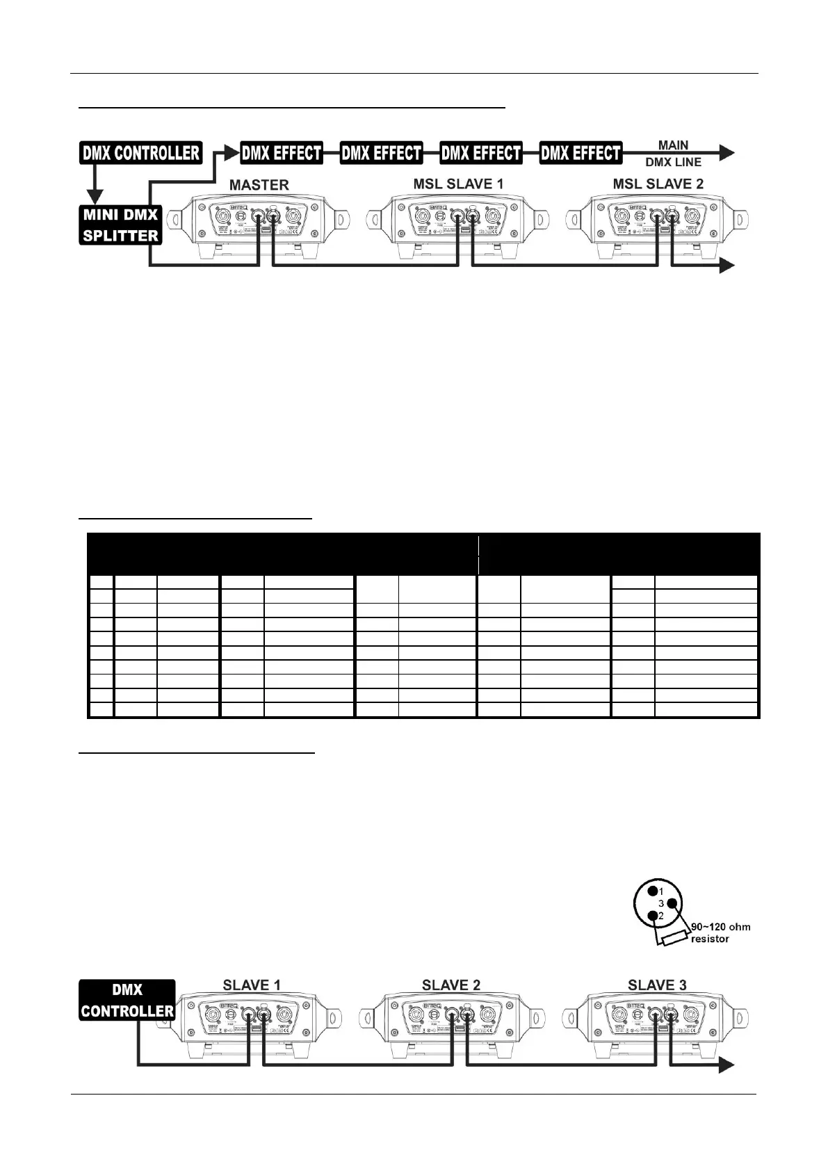
Electrical installation for two or more units in DMX-master/slave:
In this mode the units will show a synchronized show, working to the rhythm of the beat but you can still
control some functions on the master using only 5 DMX-channels.
To assure proper operation you need an optional “Mini DMX-SPLITTER” to isolate the master/slave line
from the main DMX-line, see drawing.
Connect 2 to maximum 16 units together using good quality balanced microphone cables. The first unit in
the chain will act as the master, the other units will act automatically as slaves.
Set the master to 5MSL channel mode (see previous chapter).
For the DMX-controller the master and its slaves can now be considered as 1 virtual effect that needs a
start address so it can be controlled as any other DMX-unit in the DMX chain: see “DMX Address” in the
chapter “Main Menu” to see how you can set the DMX-start address.
Make sure that all units are connected to the mains.
Set the DMX-controller according to the DMX-chart below.
Done!
Remark: in order to work well to the rhythm of the music, make sure to set the [No DMX] mode of the
MASTER projector to [SOUND] and sound sensitivity [Sound] to a value over 50 (see previous chapter).
DMX-Chart for 5MSL working mode
Electrical installation in DMX-mode:
The DMX-protocol is a widely used high speed signal to control intelligent light equipment. You need to
“daisy chain” your DMX controller and all the connected units with a good quality balanced cable.
Both XLR-3pin and XLR-5pin connectors are used, however XLR-3pin is more popular because these
cables are compatible with balanced audio cables.
Pin layout XLR-3pin:
Pin1 = GND ~ Pin2 = Negative signal (-) ~ Pin3 = Positive signal (+)
Pin layout XLR-5pin:
Pin1 = GND ~ Pin2 = Negative signal (-) ~ Pin3 = Positive signal (+) ~ Pins4+5 not used.
To prevent strange behavior of the light effects, due to interferences, you must use a 90Ω to 120Ω
terminator at the end of the chain. Never use Y-splitter cables, this simply won’t
work!
Make sure that all units are connected to the mains.
Each light effect in the chain needs to have its proper starting address so it knows
which commands from the controller it has to decode. In the next section you will
learn how to set the DMX addresses.
 Loading...