Specifications subject to change without notice. © 2013 Brivis Climate Systems Pty Ltd
2
INSTALLATION, START-UP & MAINTENANCE
INSTRUCTIONS
1.0 INTRODUCTION ...................................................................................................................... 4
1.1 Brivis ICE R410a Fixed Speed Range ..................................................................4
1.2 Safety / Warnings..................................................................................................4
1.3 Codes / Regulations ..............................................................................................5
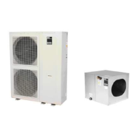
2.0 COMPONENTS ........................................................................................................................ 5
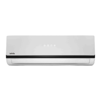
2.1 Indoor Unit (Cooling Coil) ......................................................................................5
2.2 Starting Collars......................................................................................................6
2.3 P-Trap ...................................................................................................................6
2.4 Outdoor Unit..........................................................................................................7
3.0 TYPICAL INSTALLATION........................................................................................................ 8
4.0 INDOOR COIL INSTALLATION ............................................................................................... 8
4.1 Location.................................................................................................................8
4.2 Condensate Drain / Safety Tray ............................................................................9
4.3 Minimum Service Access ......................................................................................9
4.4 System and Ductwork Design ...............................................................................9
4.5 Brivis Heater Thermistor position (if applicable) ..................................................10
4.6 Filtration ..............................................................................................................10
4.7 General Arrangement Drawings ..........................................................................10
5.0 OUTDOOR UNIT INSTALLATION ......................................................................................... 11
5.1 Location...............................................................................................................11
5.2 Electrical Connection...........................................................................................11
5.3 Thermostat Control Wiring ..................................................................................12
5.4 Wiring Diagrams..................................................................................................13
5.5 General Arrangement Drawings & Clearance Requirements ..............................16
6.0 REFRIGERATION CHARGE & PIPE-WORK ......................................................................... 16
6.1 Piping Design ......................................................................................................17
6.2 Recommended Interconnecting Pipe Sizing........................................................17
6.3 Max vertical pipe run ...........................................................................................17
6.4 Correction Factors: vapour line sizing vs. cooling capacity .................................18
6.5 Pipe-work connection ..........................................................................................18
6.6 Charging the system ...........................................................................................18
6.7 Oil Checking and Top Up ....................................................................................19
7.0 START-UP AND COMMISSIONING....................................................................................... 19
7.1 Sequence of Operation .......................................................................................20
7.2 Cooling Capacity / Air Flow .................................................................................21
7.3 Specifications ......................................................................................................23
7.4 Commissioning Sheet .........................................................................................24