Do you have a question about the Brivo ACS6100 and is the answer not in the manual?
Details Federal Communications Commission (FCC) compliancy for Class B digital devices.
Specifies RF radiation exposure limits and conditions for equipment operation.
Outlines compliance with Canadian radio standards and licensing requirements.
Provides UL294 performance levels and ULC listing compliance information.
Information on parts, service, documentation limitations, and product support.
Explains the manual's purpose, target audience, and organizational structure.
Defines essential terms used throughout the installation manual.
Details recommended wire types, gauges, shielding, and lengths for various signals.
Lists supplementary guides and contact information for technical support.
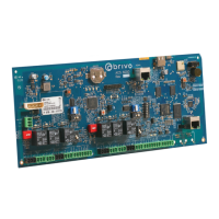
Explains the function and capabilities of the Brivo B-ACS6000-MBE/MBS control panel.
Details compatibility requirements for readers and other system components.
Checks for network compatibility and required infrastructure at the client site.
Decides the control panel's physical size based on expansion board requirements.
Calculates and determines optimal locations for control and expansion chassis.
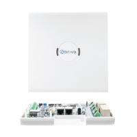
Guides on assembling and securely mounting the control and expansion chassis.
Instructions for installing a user-provided physical tamper switch.
Illustrates switch locations on the ACS6000 Main Control Board.
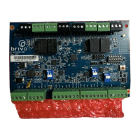
Illustrates switch locations on the ACS6100 Door Board.
Illustrates switch locations on the ACS6100 Input Output Board.
Diagram showing the location and function of SW 7 switch bank.
Details settings for tamper, CAN Bus termination, and maintenance modes.
Explains factory reset procedure and Wi-Fi enabled/disabled settings.
Wiring instructions for connecting the main control board to the power supply.
Wiring instructions for connecting expansion boards to the power supply.
Describes the tamper ON/OFF toggle and optical tamper sensor locations.
Connects a user-provided tamper switch to the main control board.
Connects tamper switches to expansion boards within each chassis.
Connects expansion boards within the control chassis to the main control board.
Guides on connecting multiple expansion chassis together using CAN bus.
Configures CAN bus address using SW1 settings on the main control board.
Details the addressing scheme for door boards on the CAN bus.
Provides wiring instructions for Wiegand readers connected to door nodes.
Connects Request-to-Exit (REX) devices and door sensors to terminal blocks.
Wiring instructions for the door lock relay terminal block.
Details wiring for auxiliary relays and inputs for various functions.
Connects reader terminals using RS-485 or Wiegand standards.
Guides for wiring OSDP readers using RS-485 Half-Duplex communication.
Locates and explains the RS-485 termination switches for doors.
Locates and explains the duplex mode selection switches for doors.
Details the setup for the Door 1 RS-485 bus termination switch.
Configures the Door 1 Wet/Dry switch for contact mode selection.
Standard wiring conventions for connecting Wiegand readers.
Standard wiring conventions for connecting OSDP readers via RS-485.
Details the wiring of inputs and outputs on the Input Output Board.
Checks power supply and control board LEDs for correct operation.
Verifies the local heartbeat LED on Door Boards indicates 12VDC power.
Verifies the local heartbeat LED on Input Output Boards indicates 12VDC power.
| Model | ACS6100 |
|---|---|
| Communication | TCP/IP, RS-485 |
| Maximum Number of Transactions Stored | 50, 000 |
| Compatibility | Brivo Onair |
| Type | Control Panel |
| Connectivity | Ethernet |
| Power Supply | 12VDC, 2A |
| Operating Temperature | 0°C to 50°C (32°F to 122°F) |
| Storage Temperature | -20°C to 70°C (-4°F to 158°F) |
| Reader Ports | 2 |
| Inputs/Outputs | 4 inputs, 2 outputs |
| Outputs | 2 Form C relays |