HOW TO INSTALL THIS SMOKE ALARM
2
• This Smoke Alarm is made to be mounted on any standard wiring junction
box up to 10 cm (4 inches) octagon size.
• This Smoke Alarm is made to be mounted on the ceiling, or on the wall if
necessary.
• These Smoke Alarms can serve as a single-station stand-alone unit or be
interconnected together.
• BRK recommends that all mains (AC) powered Smoke Alarms be
interconnected. Please read “How to Interconnect Alarms” for important
interconnect specifications. Interconnected units offer more security than
single-station stand-alone Smoke Alarms.
• Smoke Alarms should only be installed by a qualified electrician in
accordance with current I.E.E. regulations.
• The circuit used to power the Alarm must be a 24-hour 230VAC, 50 Hz
circuit. Be sure the circuit cannot be turned off by a switch or ground
fault interrupter.
• It is possible that a fire could occur on the circuit powering this Alarm.
While not likely, if this did happen the Alarm might fail to activate. Some
safety experts recommend that Smoke Alarms be wired on a separate
circuit, one with no other lights or appliances. Other safety experts
believe that it is better to put the Alarms on the same circuit as other
appliances so that it is more readily apparent if the circuit fails. BRK
recommends the use of either separate or common circuits
plus the
installation of battery powered or mains (AC) powered Smoke Alarms
with built-in battery back-up if you are concerned about the reliability of
your mains (AC) power.
Before installing this Smoke Alarm, read “Recommended Locations for Smoke
Alarms” and “Locations to Avoid for Smoke Alarms.” Then decide where to
install this Smoke Alarm.
ELECTRICAL SHOCK HAZARD: TURN OFF POWER TO THE AREA
WHERE YOU PLAN TO PUT THE ALARM AT THE FUSE BOX OR
CIRCUIT BREAKER BOX.
This Smoke Alarm shall not be exposed to dripping or splashing.
To install your Smoke Alarm, follow these steps:
1. Install a junction box or a ceiling pattress (BRK Model SMK839 or
SMK839RCB) where you plan to install the Alarm if a box is not already
installed. Use standard 1.5mm
2
solid copper cable.
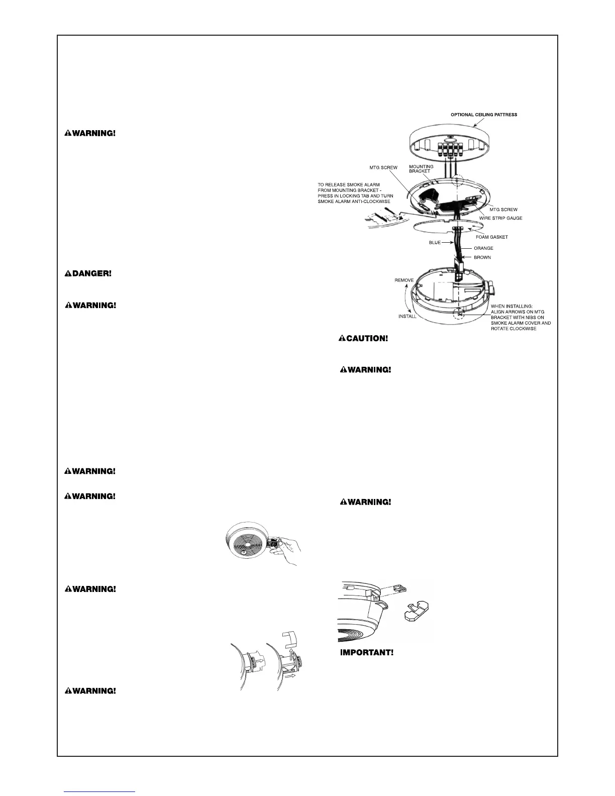
2. Install the mounting bracket on the junction box or ceiling pattress using
the screw slots that fit the junction box you are using.
3. A power connector with ORANGE, BROWN, and BLUE wires is packed
with each Alarm. Use an insulated terminal block to connect these wires to
the installation’s mains (AC) power. Connect the BROWN wire (live) on the
connector to the RED AC power wire and the BLUE wire (neutral) on the
connector to the BLACK AC wire.
NOTE: If this Alarm is to be connected to other Alarms, read the instructions
in the next section on “How to Interconnect Alarms” before you finish
installing the Alarm. If the Alarm will not be interconnected, do not use the
ORANGE wire on the connector.
4. If the Alarm WILL be connected to other Alarms, connect the ORANGE wire
on the connector to the INTERCONNECT wire. If the Alarm WILL NOT be
connected to other Alarms, insulate the stripped end of the ORANGE wire
on the connector with electrical tape and tuck it into the junction box or
ceiling pattress.
DO NOT connect the AC power wires to the INTERCONNECT terminal.
This will damage the Alarm.
MODEL 86RACEN: The battery is positioned WRONG in the factory to
keep it fresh until installation. It must be repositioned to provide DC
back-up power.
5. Grasp the tab on the battery drawer and pull it
straight out as shown in the figure.
6. Remove the battery and reposition it properly, as
indicated on the battery compartment. Push the
battery drawer back in until it is flush with the
housing.
7. Depress the test button for 20 seconds or until the alarm horn sounds.
Check battery connection if alarm horn does not sound.
If the Alarm does not work properly, make sure the battery is fresh and is in
correctly. Be sure the openings to the sensing chamber are clean. If there is still
a problem,
do not try to fix the Alarm yourself. This will void your guarantee.
8. Place the gasket on the back of the Alarm cover, being sure to line
up the cut-outs of the gasket with the power input block. The gas-
ket will only fit one way.
9.
Plug the power connector into the back of the Alarm as shown in the
figure below. It is keyed so it can only be installed one way. The con-
nector can be removed at any time by holding the connector body
firmly and pulling out.
Interconnect should not be made to any earth terminal.
10. Align the locating tab on the Alarm cover with the arrow on the rim
of the mounting bracket. Then, turn the Alarm clockwise while
exerting pressure to compress the gasket until you feel a click.
The Alarm snaps into the mounting bracket.
11.
Restore power to the junction box only if you are not going to
interconnect Alarms.
12. The Green POWER ON indicator should glow steadily when the
power is turned on. If this indicator does not glow, check all wire
connections. If power is on and connections are correct, but the
POWER ON indicator still does not glow, the Alarm should be
returned for service. Do not attempt to fix it yourself, this will void
your guarantee.
13. To make sure the Alarm is working properly, press the test button
marked “PUSH TO TEST” on the Alarm cover. Hold it for about 20
seconds until the Alarm sounds.
DO NOT connect this Alarm to any other Alarm or auxiliary device.
Connecting anything else to this Alarm will keep it from working
properly.
MODEL 86RACHE10N:
Once installed on the ceiling, you must test the unit BEFORE installing
the locking tab. Once the locking tab is in place, the drawer cannot be
reopened. If the unit does not alarm when you press the Test/Silence
button, open the drawer and try closing it again. Test the unit again.
WIRING MUST CONFORM TO I.E.E. REGULATIONS FOR
ELECTRICAL INSTALLATION
MODEL 86RACHE10N:
•
Activate the lithium cell. Remove the protective
activation tab inside the lithium cell drawer and
slide drawer into the Smoke Alarm, and insert the
locking tab shown once installed on the ceiling.
Failure to activate the Smoke Alarm will remove
your protection and invalidate your guarantee.
Alarm may activate for up to 30 seconds.
The lithium cell is protected by a removable tab in the factory to keep it
fresh until the Smoke Alarm is installed. The protective tab must be
removed before installing the Smoke Alarm or the lithium cell back-up will
not operate.
• Check for proper lithium cell (DC) back-up. Press the test button on
the Smoke Alarm cover. Hold in for about 10 seconds until the alarm
sounds. The alarm may operate for up to 10 seconds after releasing the
test button.
 Loading...