Thank you for purchasing the Host
Bus Adapter (HBA). Please take a few
minutes to read this quick
installation guide before you install
the HBA.
AT TEN TIO N: Perform all installation work at
an electrostatic discharge (ESD)-
safe workstation that meets the
requirements of EIA-625.
Requirements for Handling
Electrostatic Discharge Sensitive
Devices
. You must perform all
actions in accordance to the
latest revision of the IPC-A-610
ESD-recommended practices.
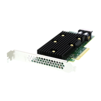
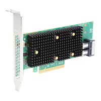
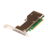
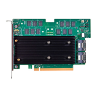
Quick Installation Guide
HBA 9400-16i and HBA 9400-8i Tri-Mode Storage Adapters
Hardware Installation Instructions
To install the Tri-Mode HBA, follow these steps:
1. Unpack the HBA, and inspect it for damage. Unpack the HBA in a static-free environment.
Remove the HBA from the antistatic bag, and carefully inspect the device for damage. If you notice any
damage, contact Broadcom or your reseller sales and support representative.
ATTENTION: Risk of data loss – To avoid the risk of data loss, back up your data before you change your
system configuration.
2. Prepare the computer. Turn off the computer, and disconnect the power supply.
CAUTION: Risk of electrical shock – Disconnect the computer from the power supply and from
any networks to which you will install the HBA, or you risk damaging the system or
experiencing electrical shock.
3. Remove the cover from the chassis.
4. Check the mounting bracket on the HBA (system dependent). If required for your system,
replace the full-profile mounting bracket that ships on the HBA with the low-profile bracket supplied.
Complete the following steps to attach the low-profile bracket.
a. Using a No. 1 Phillips screwdriver that is ESD safe, remove the two Phillips screws that connect
the full-profile bracket to the board. Unscrew the two screws located at the top and bottom edges
of the board. Avoid touching any board components with the screwdriver or bracket.
b. Remove the full-profile bracket. Do not damage the HBA.
c. Place the HBA on top of the low-profile bracket. Position the bracket so that the screw holes in
the tabs align with the openings in the board.
d. Using a No. 1 Phillips torque screwdriver that is ESD safe, set to a maximum torque of 4.8 ± 0.5
inch-pounds. Replace the two Phillips screws removed in step a.
ATTENTION: Possible hardware damage – Exceeding this torque specification can damage the board,
connectors, or screws, and can void the warranty on the board.
5. Insert the HBA into an available PCIe slot. Locate an empty x8 PCIe slot adequate for your board.
Remove the blank bracket panel on the rear of the computer that aligns with the empty PCIe slot. Save
this bracket screw, if applicable. Align the HBA to a PCIe slot. Press down gently, but firmly, to seat the
HBA correctly in the slot. The following figure shows how to insert the HBA into a PCIe slot.
NOTE: The shape, size, and locations of the components on your HBA and its bracket might vary from
this illustration. The HBA requires an x8 PCIe slot.