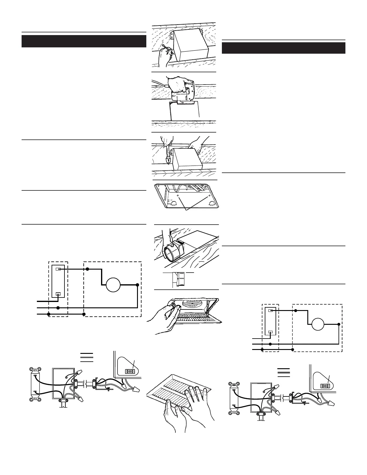
INSTALL THE HOUSING (continued)
Existing Construction
3
1. Choose the location for your fan in the ceiling. For best possible
performance, use the shortest possible duct run and a minimum
number of elbows.
2. In attic, position mounting brackets against joist. Trace outline
of housing on ceiling material.
3. Set housing aside and cut ceiling opening slightly larger than
marked.
4. Place housing in opening so that its bottom edge is flush
with finished ceiling. Nail to joist through keyhole on both sides.
To ensure a noise-free installation, drive another nail through the
top hole of each mounting bracket.
5. Additional mounting holes are provided for installations where
access from above is inconvenient or not possible. Nail or screw
housing directly to joists or framing.
ADDITIONAL MOUNTING HOLES
ORIFICIOS DE MONTAJE ADICIONALES
FLUSH
AL RAS
INSTALL THE DUCTWORK
1. Snap the damper/duct connector onto housing. Make sure that
tabs on the connector lock into slots in housing. Top of damper/
duct connector should be flush with top of housing.
2. Connect 4” round duct to damper/duct connector and extend
duct to outside through a roof or wall cap. Check damper to
make sure that it opens freely. Tape all duct connections to make
them secure and air tight.
ATTACH THE GRILLE
CONNECT THE WIRING
1. Wire unit following diagram. Run electrical cable as direct as
possible to unit. Do not allow cable to touch sides or top of unit
after installation is complete.
1. Squeeze grille springs together and insert springs into slots in
motor plate.
2. Push grille up against ceiling.
BLK
BLK
WHT
WHT
GRD
ON / OFF
SWITCH
IN
BLK
WHT
GRD
M
SWITCH BOX
ON / OFF SWITCH
WHITE
BLACK
GROUND
(bare)
WIRING
PLATE
120 VAC
Construcción existente
INSTALACIÓN DE LA CUBIERTA
(continuación)
1. Seleccione la ubicación del ventilador en el cielo raso. Para
obtener el mejor rendimiento posible, utilice un tramo de con-
ductos lo más corto posible y un número mínimo de codos.
2. En el entretecho, coloque las abrazaderas de montaje contra
la vigueta. Trace el perímetro de la cubierta en el material del
techo.
3. Coloque la cubierta a un lado y haga una abertura en el techo
ligeramente más grande que el perímetro marcado.
4. Coloque la cubierta en la abertura de manera que su borde
inferior quede al ras del cielo raso terminado. Clave la cubierta
en la vigueta a través del orificio en forma de cerradura, en
ambos lados. Para asegurar un montaje sin ruido, coloque otro
clavo en el orificio superior de cada aleta de montaje.
5. En la cubierta se pueden encontrar orificios de montaje adicio-
nales para aquellas instalaciones en las que es inconveniente
o imposible el acceso desde arriba. Clave o atornille la cubierta
directamente en las viguetas o el armazón.
CAJA DE INTERRUPTOR
ENCENDIDO /
APAGADO
(se vende por
separado)
BLANCO
NEGRO
TIERRA
(desnudo)
PLACA
DE CONEXIONES
LÍNEA DE ENTRADA
NEG
NEG
BLC
BLC
TRA
UNIDAD
CAJA DE
INTER-
RUPTOR
ENCENDIDO/
APAGADO
LÍNEA
DE
NEG
BLC
TRA
M
INSTALACIÓN DEL SISTEMA DE
CONDUCTOS
1. Conecte a presión el conector del regulador de tiro/conducto
en la cubierta. Asegúrese de que las aletas del conector queden
fijas en las ranuras de la cubierta. La parte superior del conector
del regulador de tiro/conducto debe quedar al ras de la parte
superior de la cubierta.
2. Conecte el conducto redondo de 4” (10.2 cm) en el conector
del regulador de tiro/conducto y extienda el conducto hasta
el exterior a través de una tapa de techo o de pared. Revise
el regulador de tiro para asegurarse de que abre libremente.
Coloque cinta en todas las conexiones de los conductos para
asegurarlas y hacerlas herméticas
1. Conecte la unidad con este diagrama. Extienda el cable eléctrico
a la unidad tan directamente como sea posible. No permita que
el cable toque los costados ni la parte superior de la unidad
después de que la instalación esté terminada.
CONEXIÓN DE LA REJILLA
CONEXIÓN ELÉCTRICA
1. Apriete los resortes de la rejilla y métalos en la place del motor.
2. Presione la rejilla contra el cielo raso.
 Loading...