INSTALLATION, USE & CARE INSTRUCTIONS
INSTALLATION
7
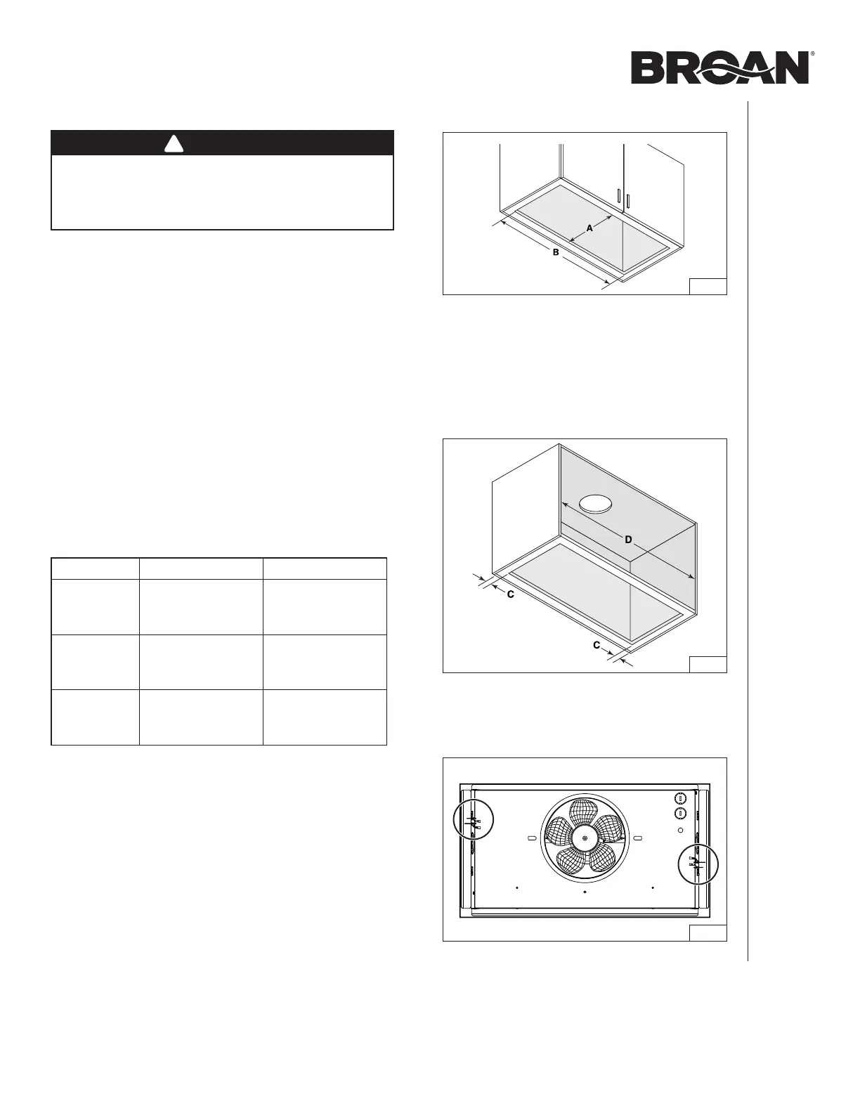
CUT A HOLE IN THE BOTTOM OF THE CABINET
FIG. 5
A = 10¼” (all units)
B = 19
9
/16” (PM300SS)
B = 22 ¹/16” (BBN1243SS)
B = 28 ¹/16” (BBN1303SS)
PREPARE THE CABINET
WARNING
The cabinet must be secured to wall studs or other
wooden framework behind the drywall to support
the weight of this unit. Failure to do so may cause
personal injury or damage to countertop or cooktop.
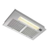
NOTES: A. The unit has to be installed inside the cabinet. If
installing with one of the optional liners (PM300SS
unit only), use it as a template to cut the hole in
the bottom of the cabinet.
B. The unit should be mounted centered laterally
over the cooktop burners.
C. For back to front position, the unit must be
mounted according to local building codes.
1. Cut a hole in the bottom of the cabinet, using the
dimensions shown (FIG. 5), or use the optional liner as a
template (PM300SS unit only).
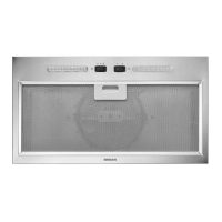
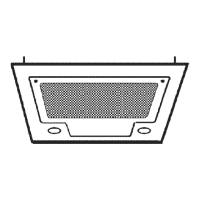
2. PM300SS unit only: Where needed, install the metal liner.
3. Measure the remaining material of the cabinet bottom sides
(C) (FIG. 6), if it is 1/4” or more, there is no need to use
the cabinet brackets. Go to step 8 on page 9.
4. If there is less than 1/4” remaining material (C), carefully
remove those strips. Measure the cabinet inner width (D)
(FIG. 6). Refer to the table below to see which cabinet
bracket edge configuration must be used.
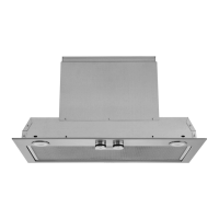
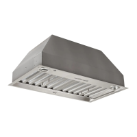
5. Locate the Ease of Install hooks (circled in FIG. 7) on the
unit. Temporary insert the unit in the cabinet, while holding
the unit, mark the position of the Ease of Install hooks
(shown as E in FIG. 8 on next page) on both cabinet side
walls. Remove the unit.
Unit narrow edge wide edge
PM300SS
D
From 19-9/16”
to < 20”
D
From 20”
to 20-1/2”
BBN1243SS
D
From 22-1/16”
to < 22-1/2”
D
From 22-1/2”
to 23”
BBN1303SS
D
From 28-1/16”
to < 28-1/2”
D
From 28-1/2”
to 29”
FIG. 6
FIG. 7
FRONT
UNIT TOP VIEW