INSTALLATION, USE & CARE INSTRUCTIONS
INSTALLATION
9
PREPARE THE CABINET (cont’d)
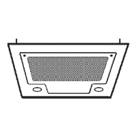
7. Measure the distance between both bottom bracket
edges (F) (FIG. 10). The table below shows the approriate
distance needed.
Unit narrow edge wide edge
PM400SS
F
From 19-3/8”
to < 19-9/16”
F
From 19-9/16”
to 19-13/16”
BBN2243SS
F
From 21-7/8”
to < 22-1/16”
F
From 22-1/16”
to 22-516”
BBN2303SS
F
From 27-7/8”
to < 28-1/16”
F
From 28-1/16”
to 28-5/16”
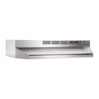
If the measured distance needs to be shortened, screw two
no. 8-32 x 1/4” machine screws, in each bottom embossed
cabinet brackets hole; this will slightly bend the bottom part
of the brackets (FIG. 11). Screw both brackets until the
appropriate distance is obtained.
5¼"5¼"
3½"
3/4"
FIG. 13
CABINET BACK WALL
CABINET BOTTOM
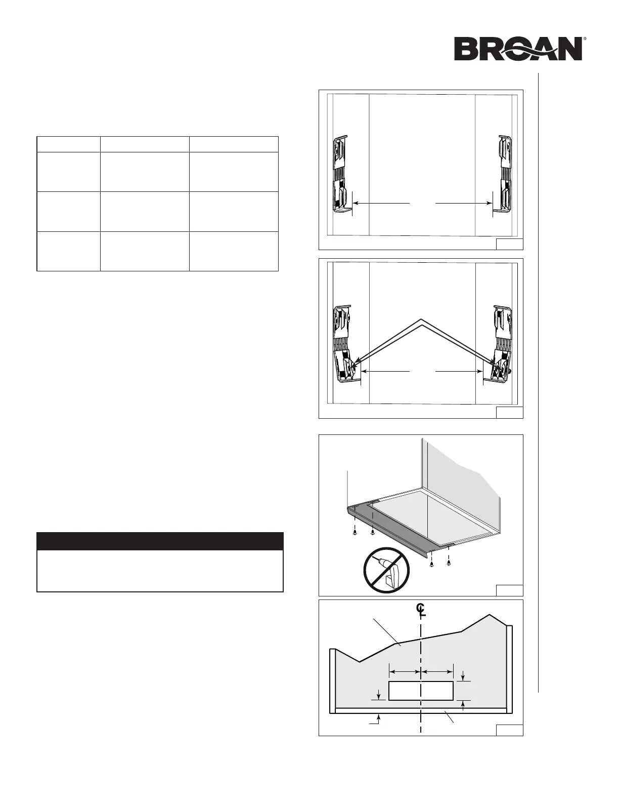
BBn2243SS and BBn2303SS unitS only:
8. There are 3 different sizes of filler included with these units,
designed to fit up to 13-in. depth cabinets. For up to 15-in.
depth cabinets, another set of 4 fillers is available (for
BBN2243SS unit, order: HADTBN24, for BBN2303SS:
order HADTBN30). Choose the filler that fits to cover the
back bottom edge of the cabinet. Use 4 no. 6 x 3/4” truss
head wood screws (included) to mount it (FIG. 12).
Horizontal exHauSt inStallation only (all unitS)
This powerpack insert is factory shipped to exhaust vertically;
however, it is possible to make it exhaust horizontally (3¼” x 10”
ducting only).
9. Cut the hole for the horizontal exhaust through the back
wall of the cabinet using the dimensions shown. (FIG. 13).
FIG. 12
CAUTION
Never use an electric screwdriver or drill to screw the
filler to the bottom edge of cabinet; use a standard
screwdriver.
F
FIG. 10
F
FIG. 11
Screws in bottom
embossed holes
 Loading...