EasyManua.ls Logo

BRONKHORST E-7000 Series User Manual

BRONKHORST E-7000 Series
33 pages
To Next Page IconTo Next Page
Page #1 background imageLoading...
Page #1 background image
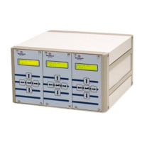
Instruction manual
Temperature
control system
for CEM
Doc. no.: 9.17.017F Date: 25-07-2011
ATTENTION
Please read this instruction manual carefully before installing and operating the instrument.
Not following the guidelines could result in personal injury and/or damage to the equipment.

Questions and Answers:

BRONKHORST E-7000 Series Specifications

General IconGeneral
Protection RatingIP40
Control RangeDepends on the connected instrument
Response TimeDepends on the connected instrument
Power Supply+15 Vdc / -15 Vdc / +24 Vdc (depending on model)
Supply voltage+15 Vdc / -15 Vdc / +24 Vdc (depending on model)
CommunicationRS232

Summary

Warranty

1 INTRODUCTION

1.4 In/Output signals

Covers connection details for input/output signals and signal types.

2 OPERATION

2.5 Operation menu

Covers setting the operation mode, setpoint source, fluidset, and slope.

2.7 Alarm menu

Details various alarm settings, modes, limits, relay actions, and delay.

2.8 Instrument menu

Explains how to configure instrument type, sensor, capacity, fluid, and control settings.

2.10 FLOW-BUS menu

Details how to install, start, stop, and check settings for FLOW-BUS communication.

2.11 Calibration with polynomial functions

Explains general information, form, and presentation of polynomial functions for calibration.

4 TROUBLESHOOTING