Bronkhorst®
Instruction Manual EL-FLOW® Prestige9.17.084N 17
3.1.2 Valve Safe State
When a controlling instrument is not powered or cannot communicate with the fieldbus network (if applicable), the control
valve automatically returns to its default state (also called Safe State), which is closed for a 'normally closed' valve (n/c) and
fully open for a 'normally open' valve (n/o). Taking into account the typical process conditions under which the instrument
is used (such as the processed media and ambient conditions; see also Intended use), the default state is generally
considered safe.
Check the serial number label or the technical specifications to see which valve type is used on your instrument (if
applicable).
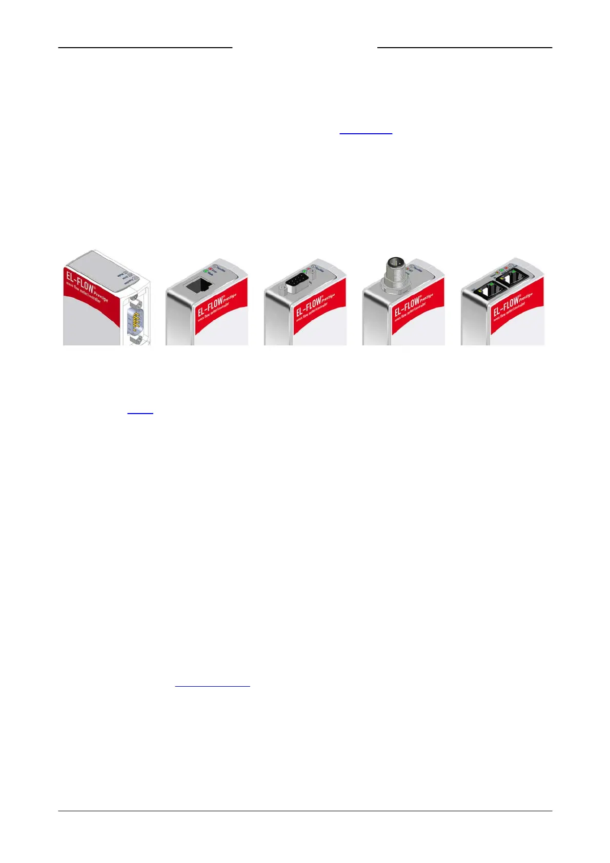
3.2 Communication interfaces
Numerous input/output options can be installed on EL-FLOW® Prestige instruments via both the 9-pin D-sub connector on
the side of the instrument and the optional fieldbus connector on top of the instrument.
Analog and RS232
(or RS485)
F LO W - BUS or
Modbus ASCII / RTU / TCP
Et he rCA T®, PROF INE T
or EtherNet/IP
The standard 9-pin D-sub connector provides the following communication interfaces:
· Analog (0…5 Vdc; 0…10 Vdc; 0…20 mA or 4…20 mA)
· Digital RS-232 (ProPar) or RS-485 (FLOW-BUS or Modbus)
Additionally, the instrument can be provided with one of the following optional digital fieldbus interfaces:
· FLOW-BUS
· Modbus (ASCII / RTU / TCP)
· PROFIBUS DP
· EtherNet/IP
· CANopen
· DeviceNet™
· EtherCAT®
· PROFINET
The default communication protocol of the instrument (analog, digital RS-232 or fieldbus) is specified at ordering time.
3.2.1 Using multiple interfaces
The analog interface is always present on EL-FLOW® Prestige instruments. An interface to any available field bus is optional.
Operation via analog interface, RS232/RS485 (side connector) and an optional fieldbus (top connector) can be performed at
the same time. When using multiple interfaces, reading of parameters can be done simultaneously. When changing a
parameter value, the last value sent by any of the interfaces will be valid.
Control mode
A controller setpoint is accepted from either the analog or digital interface, but not both. Analog or digital operation is
selected at ordering time and is indicated on the serial number label. The inactive setpoint source is indicated between
brackets (see example below). The parameter Control Mode indicates from which source a controller setpoint is accepted:
analog or digital. See section Special parameters for more information regarding the Control Mode parameter.
Factory communication settings
The factory selected communication and side connector pinning settings are indicated on the serial number label. See
example below for a description of the communication information:

 Loading...