NO.
IN
CHAPTER
8
FLOWCHART
AND
ERROR
STATUS
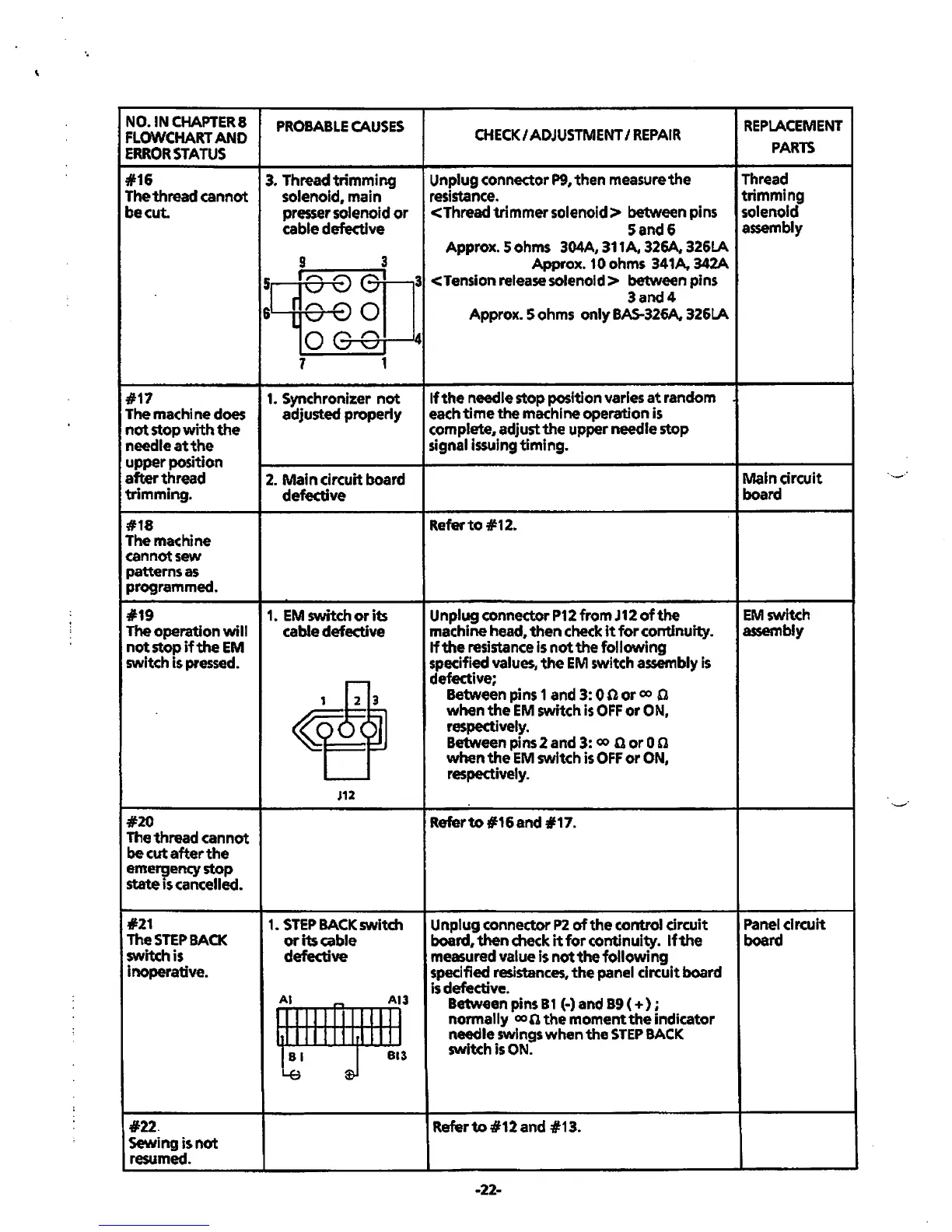
#16
The thread cannot
be
cut.
PROBABLE
CAUSES
3.
Threadtrimming
solenoid, main
presser solenoid
or
cable defective
CHECK/
ADJUSTMENT
I
REPAIR
Unplug connector
P9,
then
measure
the
resistance.
<Thread trimmer
solenoid>
between pins
Sand&
Approx. Sohms 304A, 311A, 326A. 326LA
9
3 Approx. 10 ohms 341A, 342A
5]
I 0 B
e....;...r.-
1
-----.3
<Tension release
solenoid>
between pins
r
3and4
6 l C 0 Approx. 5 ohms
only
BAS-326A. 326LA
OGC
1 1
#17
1.
Synchronizer
not
The
machine does adjusted properly
not
stop
with
the
needle
at
the
upper position
after
thread
2.
Mal n circuit board
trimming. defective
#18
The machine
cannot sew
patterns as
programmed.
4
If
the
needle stop position varies
at
random
each
time
the ma<hine operation is
complete, adjust
the
upper needle stop
signal issuing timing.
Refer
to
#12.
REPLACEMENT
PARTS
Thread
trimming
solenoid
assembly
Main
circuit
board
Unplug connector
P12
from
J12
of
the
EM
switch
machine head, then
check
it
for
continuity. assembly
#19
1.
EM
switch
or
its
The operation
will
cable defective
not
stop if
the
EM
switch is pressed.
#20
The thread cannot
be
cut
after
the
emergency stop
state
is
cancelled.
#21
The
STEP
BACK
switch is
inoperative.
#22.
Sewing is
not
resumed.
J12
1.
STEP
BACK
switch
or
its cable
defective
Al
r-.
Al3
II
IIIIIIIIIJJ
I
hllllllllrlllll
~I
J Bl3
If
the
resistance is
not
the
following
specified values,
the
EM
switch assembly
is
defective;
Between pins 1 and 3:
0
nor
co 0
when
the
EM
switch
is
OFF
or
ON,
respectively.
Between pins 2 and 3: co Q
oro
n
when
the
EM
switch
is
OFF
or
ON,
respectively.
Referto#16and
#17.
Unplug connector
P2
of
the
control
drcuit
board,
then
check
it
for
continuity.
If
the
measured value is
not
the
following
specified resistances,
the
panel circuit board
is
defective.
Between pins B 1
(·) and
B9
(
+)
;
normally co 0
the
moment
the
indicator
needle
swings
when
the
STEP
BACK
switch is
ON.
Referto#12and
#13.
-22-
Panel circuit
board
..._·
 Loading...