
J
John KingAug 3, 2025
What to do if my Brother MD-602 Engine motor won't operate?
- KKeith MartinezAug 3, 2025
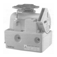
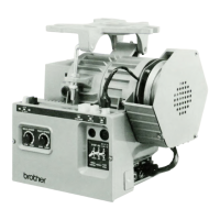
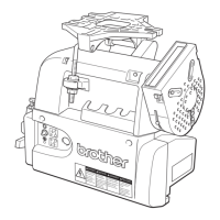
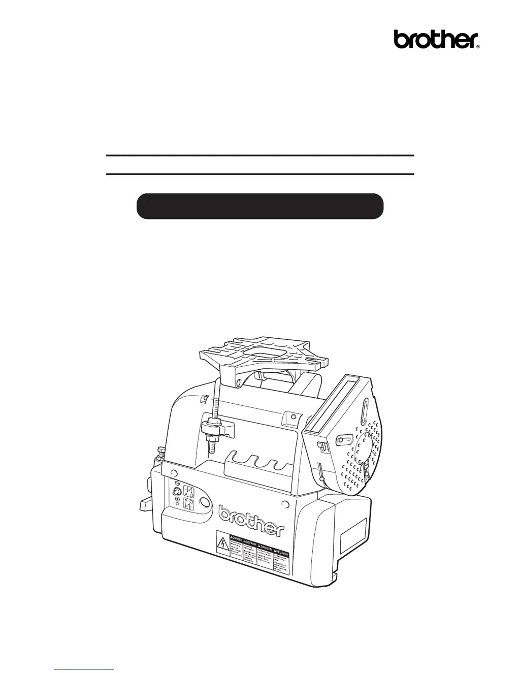
If the Brother Engine motor won't operate, even with power on and the treadle depressed, there are several potential causes. First, check if the power indicator (green LED) is illuminated. If not, verify the main power voltage by trying a different outlet. Also, check for a blown 8A fuse. If the LED is illuminated, ensure the treadle is returned to the neutral position after powering on before starting. Finally, manually turn the machine pulley; if it's heavy or doesn't rotate, inspect the machine or motor.