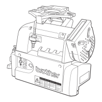
EasyManua.ls Logo

Brother MD-612 User Manual

Brother MD-612
76 pages
To Next Page IconTo Next Page
Page #1 background imageLoading...
Page #1 background image
MD-600 Series
AC Servomotor for Industrial Sewing Machines
SERVICE MANUAL
MD-602
(Single-Phase Power Specifications)
MD-612
(Three-Phase Power Specifications)

Table of Contents

Questions and Answers:

Brother MD-612 Specifications

General IconGeneral
BrandBrother
ModelMD-612
CategoryEngine
LanguageEnglish

Summary

Safety Instructions

Safety Indications and Their Meanings

Explains safety indications and symbols used in the manual and on the machine.

Cautions With Regard to Safety

Warning Label

Outline

Features

Describes key features of the MD602/MD612 servomotor, including output and torque.

Combination with Brother Sewing Machines

Lists compatible Brother sewing machine models for the MD600 series motor.

Options

Lists available optional accessories for the MD600 series motor.

Operation Panel and Options

Attachable Operation Panels

Details the F-20, F-40, and F-100 operation panels and their compatibility.

Attachable Options

Lists additional options like standing work pedals and material edge sensors.

Model Configuration

Panel Type and Treadle Type

Explains how panel and treadle types are determined by model configuration codes.

Compatible Head Settings

Lists compatible sewing machine heads and their corresponding settings.

Name Plate Explanation

Control Box Name Plate

Details the information found on the control box name plate.

Motor Name Plate

Explains the details provided on the AC servo motor name plate.

Installation

Installing the Motor to the Work Table

Provides step-by-step instructions for mounting the motor onto the sewing machine work table.

Attaching the Belt

Details the procedure for attaching and tensioning the V-belt between the motor and machine pulleys.

Installing the Belt Cover

Instructions for installing the belt cover and its safety mechanisms.

Connecting the Connecting Rod

Explains how to connect the connecting rod to the treadle lever.

Adjusting Belt Cover Safety Mechanisms

Guides on adjusting the belt casting prevention guide and finger guard.

Connecting Cords

Covers connecting power cords, switches, ground cords, and motor/control box cables.

Connector Wiring Diagrams

Installing the Head Lamp

Connecting the External Operation Panel

Treadle Unit Adjustments

Operating the Treadle

Explains how the treadle controls speed, thread trimming, and presser foot lift.

Treadle Operation (Two-Stage)

Details treadle operation for machines with two forward and two rear stages.

Adjusting Treadle Pressure and Stroke

Guides on adjusting treadle pressure, return pressure, and stroke.

Automatic Presser Foot Lifter Usage

Explains how to adjust settings when using the automatic presser foot lifter device.

Control Box Usage

Pre-Power Checks

Lists essential checks before turning on the power switch for the control box.

Power Switch and Indicator

Explains the function of the power switch and the status of the power indicator LED.

Setting Sewing Speed

Describes how to adjust the sewing speed using the control box speed adjustment knob.

DIP Switch Setting Procedure

Step-by-step guide for setting the control box DIP switches.

Function Descriptions

Table detailing functions available with no panel, F-20, F-40, and F-100 panels.

Backtacking Functions (Control Box)

Explains start and end backtacking functions when using the control box without an operation panel.

Setting Backtack Stitch Count (DIP Switches)

Guides on setting the number of start and end backtack stitches using DIP switches.

Other DIP Switch Functions (SW1)

Explains functions controlled by DIP switch SW1, including presser foot and pulley settings.

Other DIP Switch Functions (SW6)

Details speed settings controlled by DIP switch SW6 for single-needle and twin-needle machines.

Connecting Options

Connecting Standing Operation Pedals

Instructions for connecting variable-speed and two-speed standing pedals.

Pedal Connector Wiring

Illustrates the connector wiring diagrams for variable-speed and two-speed pedals.

Connecting the Material Edge Sensor

Details connection procedures for built-in and external material edge sensors.

Using the F-40 Operation Panel

F-40 Panel Layout and Keys

Identifies the parts and functions of the F-40 operation panel keys and displays.

F-40 Panel Key Functions

Explains the specific functions of each key on the F-40 operation panel.

Changing Head Settings

Setting Motor Pulley Size and DIP Switches

Guides on setting pulley size and DIP switches based on the sewing machine head.

Setting Maximum Speed (DIP Switches)

Details DIP switch settings for maximum speed adjustment for single-needle machines.

Setting Maximum Speed (Twin Needle)

Explains DIP switch settings for maximum speed for twin-needle machines.

Control Box Head Setting Procedure

Step-by-step guide to set the control box head setting based on the machine head.

Control Box Speed Settings by Head

Table showing speed settings for various heads (single needle and twin needle).

Changing Function Settings

Memory Switch Setting Example

Provides examples for changing memory switch settings for specific sewing functions.

Parameter Setting Example

Demonstrates how to change parameter settings, e.g., for motor startup delay.

Adjustments

Synchronizer Model Adjustments

Details adjustments for synchronizer models like DB2-B737/B748/B774/B791.

Troubleshooting Guide

Error Display and Details

Lists error codes displayed on the operation panel and their meanings/causes.

Motor Operation Troubleshooting

Addresses issues like motor not operating, not at high speeds, or stopping during sewing.

Needle Position Troubleshooting

Explains how to troubleshoot problems with needle stop position accuracy.

Detailed Error Code Explanations

Provides detailed explanations for various error displays like PE, OU, OL, LO, FU, etc.

Control Box Troubleshooting

Lists common problems related to the control box and their solutions.

Treadle Unit Troubleshooting

Covers troubleshooting steps for the treadle unit not starting or having incorrect voltage.

Synchronizer Troubleshooting

Addresses issues with the synchronizer, such as error signs or motor running problems.

Control PCB Troubleshooting

Troubleshooting steps for issues related to the control PCB, including fuse checks.

Power Transformer Troubleshooting

Guides on troubleshooting the power transformer, particularly when the LED does not illuminate.

Checking Machine Solenoids

Procedures for checking solenoids (reverse, wiper, trimming, presser foot) using a tester.

Checking the Motor

Instructions for checking the motor's resistance values using a tester.

Treadle Unit VR1 & VR2 Settings

VR1 & VR2 Adjustment Points

Explains the points of adjustment for VR1 and VR2 on the treadle unit.

Treadle Voltage and Display Settings

Details how to set treadle voltage and display values using VR1 and VR2.

Stroke-Voltage Chart

Chart illustrating the relationship between treadle stroke and analog voltage.

Stroke-RPM Chart

Chart showing the correlation between treadle stroke and motor RPM.

Explanation of Modes

Initialization Mode

Explains how to initialize data on the control PCB to factory settings.

Head Setting Mode

Describes how to set the control box to match the sewing machine head specifications.

Memory Switch and Parameter Setting Modes

Explains how to change functions and parameters using memory switch and parameter modes.

Stitching Speed Setting Mode

Details how to adjust various stitching speeds using the stitching speed setting mode.

Stitching Speed Types and Ranges

Table listing different stitching speed types, their display units, ranges, and remarks.

Operational Instructions

Power Switch ON Operations

Describes actions and checks when the power switch is turned ON.

Power Switch OFF Operations

Notes on operations and safety precautions when the power switch is OFF.

Pedal Operation

Explains how the treadle unit outputs voltage and how the motor starts based on pedal position.

Motor Operation While Running

Details motor control, error codes (P, Lo, PU), and voltage monitoring during operation.

Memory Switch List

Memory Switch Settings (Display No. 01-18)

Lists memory switch functions from Display No. 01 to 18 and their settings.

Memory Switch Settings (Display No. 21-38)

Lists memory switch functions from Display No. 21 to 38 and their settings.

Memory Switch Settings (Display No. 41-58)

Lists memory switch functions from Display No. 41 to 58 and their settings.

Memory Switch Settings (Display No. 61-78)

Lists memory switch functions from Display No. 61 to 78 and their settings.

Parameter List

Parameter Settings (Display No. F0-F9)

Lists parameters from F0 to F9, their initial data, setting ranges, and details.

Parameter Settings (Display No. C0-H2)

Lists parameters from C0 to H2, their initial data, setting ranges, and details.

Parameter Settings (Display No. P0-P5)

Lists parameters from P0 to P5, their initial data, setting ranges, and details.

Parameter Settings (Display No. 76-R32)

Lists parameters from 76 to R32, their initial data, setting ranges, and details.

Panel Display Table

7-Segment Display Characters

Table showing 7-segment display characters and their corresponding alphabetic/symbolic representations.

Control Box Removal

Control Box Removal Procedure

Step-by-step instructions for safely removing the control box from the motor.

Related product manuals