Do you have a question about the Brother P-touch 65 and is the answer not in the manual?
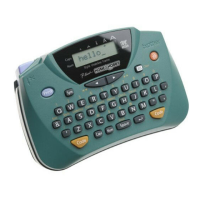
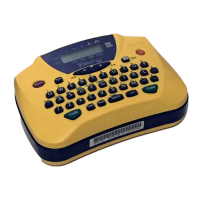
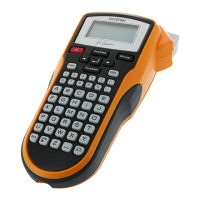
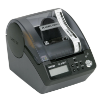
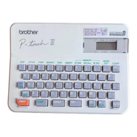
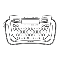
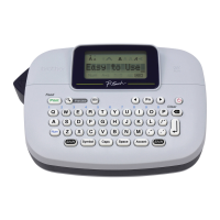
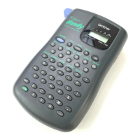
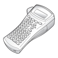
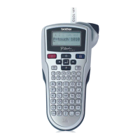
Details the physical characteristics of the P-touch 65, including dimensions, weight, keyboard, display, printing mechanism, tape cassette, and cutter.
Outlines the electronic specifications of the P-touch 65, covering character generator capabilities and power supply details.
Explains the functional principles of the P-touch 65's core mechanisms: print head, platen setting, tape feed, and cutter safety lock.
Provides detailed procedures for taking apart and putting back together the P-touch 65, including safety precautions and screw tightening torque values.
Introduces the electronic architecture of the P-touch 65, detailing the main PCB, motor, thermal print head, LCD, and the function of the sub PCB.
Details the main PCB, its block diagram, CPU, LCD controller, and specific circuits for power, motor drive, thermal head, and voltage detection.
Provides guidance on diagnosing and rectifying common P-touch 65 problems, including precautions, post-repair checks, and troubleshooting flows.
Presents detailed circuit diagrams for the Main PCB and the Sub PCB, crucial for understanding the device's electrical design and troubleshooting.
| Print Technology | Thermal Transfer |
|---|---|
| Tape Width | 9mm, 12mm |
| Keyboard | ABC |
| Print Resolution | 180 dpi |
| Print Speed | 7.5 mm/sec |
| Symbols | 71 |
| Styles | Normal, Bold, Outline, Shadow, Italic |
| Power Source | 6 x AAA batteries (LR03/HR03) (not included) |