5 - 3
SERVICE section 5
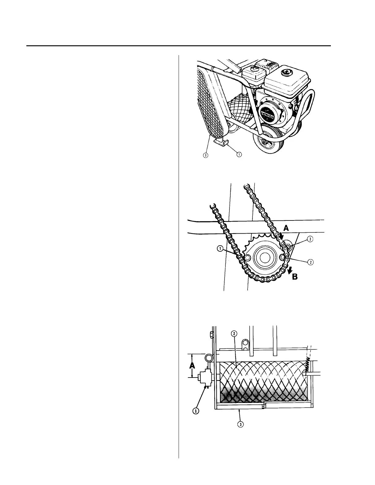
Drawing 7
Drive Chain Adjustment/Replacement
See Drawing 7. Place machine on it's kickstand (1).
Remove the chain guard (2).
See Drawing 8. Slacken off the roller support
bearing housing bolts (1) & (2) and the eccentric
washer retaining bolts (3), on both sides of the
machine. Tap the bearing flange at point “A” to pivot
the bearing in the direction of arrow “B” and so
tightening the chain. Adjust the chain until there is
1/4 inch deflection between sprocket centers.
Re-tighten the bolts (1) & (2). Turn the eccentric
washers until they are hard against the bearing
flange and tighten the bolt (3).
See Drawing 9. NOTE: When adjusting the roller
bearings (1), it is important that the roller (2) remains
parallel to the cutting blades (3). check that
dimension “A” is equal on both sides of the machine.
Failure to do so may result in uneven thickness of
cut and premature chain wear or breakage.
Drawing 8
Drawing 9