143
ELECTRICAL AND IGNITION
CHARGING SYSTEM TESTS
6
Following the manufacturer’s directions, connect
the variable load tester (carbon pile) across the
battery terminals. Stevens model LB-85 and
Snap-On model MT540D are examples of testers
available.
Start the outboard and run it at approximately
5000 RPM. Use the variable load tester to draw
the battery down at a rate equivalent to the sta-
tor’s full output.
• The ammeter should indicate nearly full output,
Approximately 50 A (or 25 A for each output) @
5000 RPM.
Decrease the battery load toward 0 A.
• Ammeter should show a reduced output. As the
current draw decreases, the battery voltage
should stabilize at approximately 14.5 V.
• If results vary, check stator BEFORE replacing
the EMM. See STATOR TESTS on p. 141.
55 V Alternator Circuit
STEP 1
Check battery ground cable for continuity.
STEP 2
With the key switch ON, check battery voltage at
battery (12 V), then check voltage on white/red
wires at J2 connector of EMM. Use Electrical Test
Probe Kit, P/N 342677 and a multimeter set to
read 55 VDC. Voltage at EMM connector should
be approximately 30 V.
WARNING
Excessive battery discharge rates might
overheat battery causing electrolyte gas-
sing. This might create an explosive atmo-
sphere. Always work in a well ventilated
area.
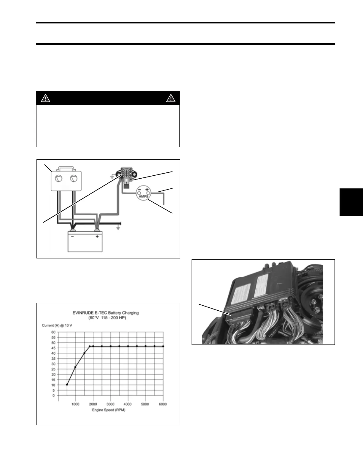
Variable Load Test Diagram
1. Red wire (alternator output from EMM)
2. Starter solenoid
3. Battery cable terminal (B+)
4. Variable load tester
5. Ammeter
002077
Battery Charging Graph 005193
2
1
5
4
3
1. J2 connector 005235
1