Subsection XX (COMMUNICATION TOOLS AND B.U.D.S.)
PROCEDURES
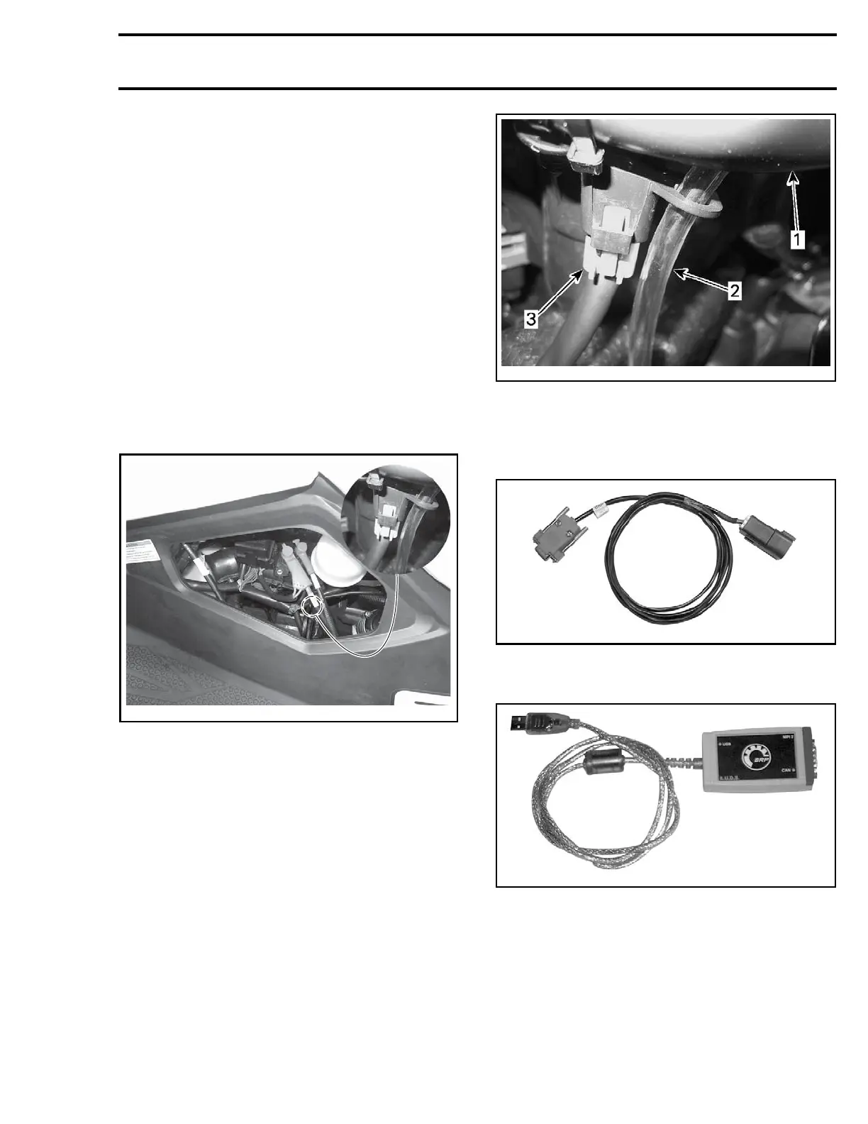
MULTI-PURPOSE INTERFACE-2
(MPI-2)
The MPI-2 (Multi-Purpose Interface-2) in conjunc-
tion with the MPI-2 diagnostic cable is used with
B.U.D.S. software to communicate with the ECM
(engine control module) and other modules.
MPI-2 Power
The MPI-2 interface card uses the power from the
PC computer USB port.
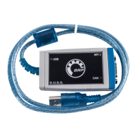
Diagnostic Connector Location
The 6-pin diagnostic connector is located near the
coolant tank, stored in it's protective cap. To ac-
cess it, remove the LH access cover.
smr2014-026-001_a
DIAGNOSTIC CONNEC TO R LOCATION
Connecting the PC to the Vehicle
1. Disconnect the 6-pin diagnostic connector from
its holder (protective cap).
smr2014-026-002-a
1. Coolant ta
nk holder
2. Coolant tank overflow hose
3. Diagnostic connector
2. Connect o
ne end of the
MPI-2 DIAGNOSTIC CA-
BLE (P/N 7
10 000 851)
to vehicle connector.
7100008
51
3. Connect the other end of diagnostic cable to the
MPI-2 INTERFACE C ARD (P/N 529 036 018).
529036018
NOTE
: An optional
MALE-FEMALE EXTENSION SE-
RIAL
CABLE (P/ N DB9)
available at electronic retail
outl
ets can be used between diagnostic cable and
MPI-
2 interface. Do not exceed 7.6 m (25 ft).
smr2014-026 3