SECTION 06 - DRIVE SYSTEM
MMC2005-001_06A.FM 06-69
DISASSEMBLY
7, Brake Pad
Only brake pads are available as spare parts. If cal-
iper or master cylinder are damaged, replace each
of them as an assembly.
CLEANING
Clean all metal components in a general purpose
solvent. Thoroughly dry all components before as
-
sembling.
CAUTION: Do not clean brake pads in solvent.
Soiled brake pads must be replaced by new ones.
INSPECTION
7, Brake Pad
CAUTION: Brake pads must always be replaced
in pairs.
Brake pads must be replaced when lining is 1 mm
(1/32 in) thick or less. Refer to the photo in BRAKE
PADS REPLACEMENT.
17, Brake Disc
Check for scoring, cracking or bending, replace as
required.
CAUTION: Brake disc should never be machined.
INSTALLATION
Apply anti-seize lubricant (P/N 293 800 070) on shaft.
The disc hub exceeds the disc more from one side
than from the other. Install disc with the longer
exceeding portion toward driven pulley.
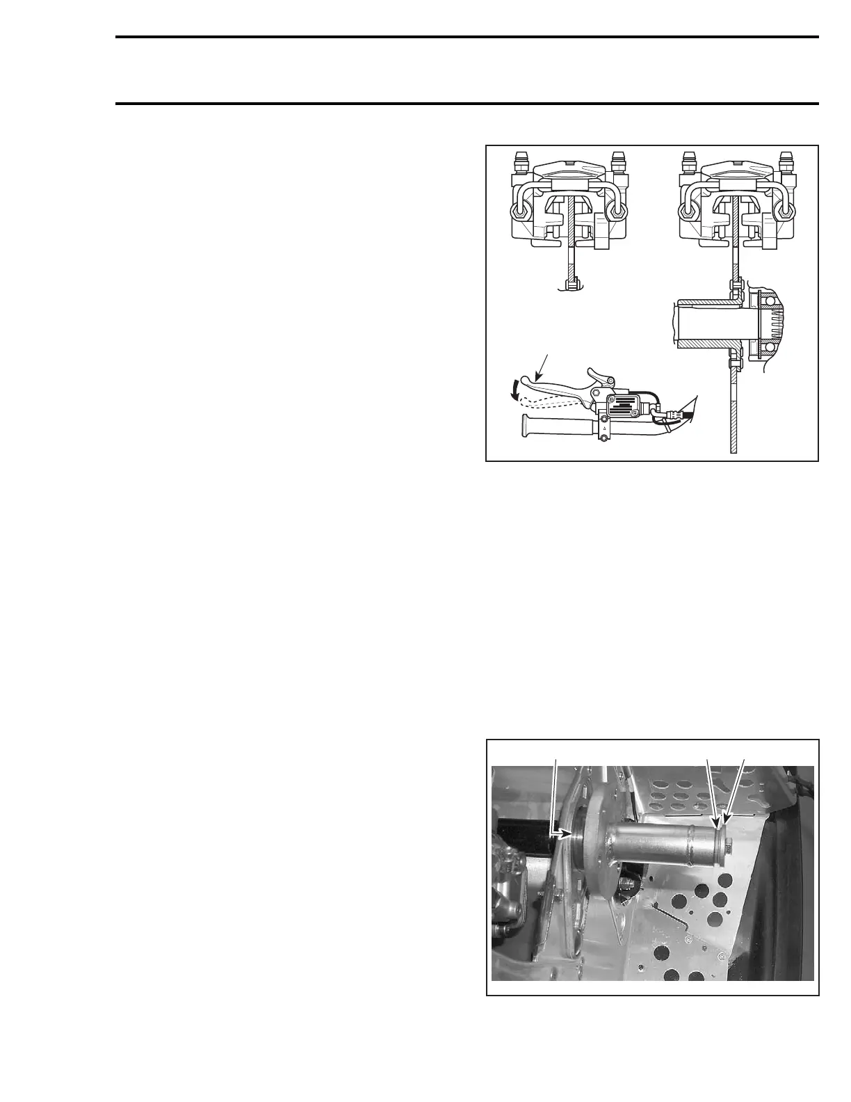
7, Brake Pad
After brake pads installation, brake disc must be
centered in caliper. Apply brake then check for prop
-
er brake disc positioning.
Push on appropriate caliper piston in order to move
pad inward allowing proper brake disc positioning.
1. Brake disc not centered
2. Brake disc centered
3. Apply brake before checking
Apply brake then recheck.
Countershaft Bearing Adjustment
Insert countershaft (with brake disc) from chain-
case side through countershaft support (driven
pulley side), then insert into chaincase.
Install countershaft bearing no. 4 using proper tool.
To install bearing on countershaft, use remover
(P/N 529 030 100) and some flat washers of 3
mm
(1/8
in) total thickness. Using original retaining
screw and shouldered washer tighten until bear
-
ing rests against circlip.
1. Washers use as a 3 mm (1/8 in) spacer
2. Original retaining screw and shouldered washer
3. Bearing against circlip
1
A03D2KA
2
3
A33D0YA
213
 Loading...
