Chapter 2 — Controls and Connections
Front Panel
BE 1300– 12 Dual Microphone Supply Type 5935 2–3
User Guide
2.1.2 Switches
2.1.3 Gain Adjustment
2.1.4 Signal Connectors
On/Off:
applies power to the unit from the power-supply input section of the
unit. It should be noted that the switch comes after the external supply
voltage regulator. This means it is possible to recharge the batteries
whilst the unit is apparently off.
swaps the output sockets on the front panel with the channel outputs
inside the unit. When in the cross position, the output of channel 1 is
sent to the Ch.2 front panel output socket, and the output of channel
2 is sent to the Ch.1 front panel output socket. The rear-panel sockets
remain unaffected.
A/Lin.: sends either the A-weighted signal (A) or the un-weighted signal (Lin.)
from the amplifier AC-coupled output to the front-panel output socket.
The rear- panel sockets remain unaffected.
Gain dB
:
this knob selects the channel gain in steps of 10 dB from 0 dB to +50 dB.
Sens. Adj.: this screwdriver adjustment allows the gain of the channel to be
continuously varied over a range of ± 5 dB.
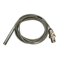
Input: a standard Brüel & Kjær 7-pin preamplifier socket is provided for each
channel. When plugged in, the preamplifier receives its drive voltage,
the microphone-capsule polarization voltage, and the microphone
heater voltage (if applied on rear panel) from the Type 5935 power
supply. The preamplifier output signal also passes into the unit’s
amplifiers through this connector.
Output
:
the AC-coupled output of each channel appears on unbalanced BNC
sockets. The source of the signal, Ch.1 or Ch.2, depends upon the
position of the changeover switch. The type of signal, Lin. or A-
weighted, depends upon the position of the A/Lin. switch.
 Loading...