Chapter 3 — Operation
Input Connection
BE 1300– 12 Dual Microphone Supply Type 5935 3–5
User Guide
ry of almost any connected instruments. Suitable screened leads, for example
Brüel & Kjær BNC to BNC cable AO 0087, give the best noise immunity.
The choice of which outputs to use depends upon the application at the time, but
some guidelines are:
● In a fixed rack-mounted system, the connectors at the rear of the unit are
hardwired to the next piece of equipment in the chain. The front panel outputs
can than be used for monitoring the signal at the output of the unit.
● When it is known that the following piece of equipment is sensitive to DC offset,
the AC-coupled outputs on the front panel are used. The output capacitors re-
move any DC component from the signal.
It should always be remembered that there is an output swap switch for the front
panel outputs, which could cause confusion if an expected output appears on the
wrong channel.
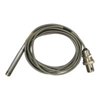
3.5 Input Connection
Input to the Type 5935 is via a Brüel & Kjær 7-pin preamplifier socket. The connec-
tions to this socket are shown below.
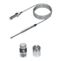
All standard Brüel & Kjær preamplifiers can be connected to this socket, except the
Type 2660. Via this socket the preamplifier receives the required power to drive the
internal preamplifier circuitry, together with microphone polarization voltages and
heater power (if applied).
Fig.3.3 Internal view from bottom, showing fuse holder and polarization switch
fuse holder
polarization voltage switch
 Loading...