Technical data
and startup
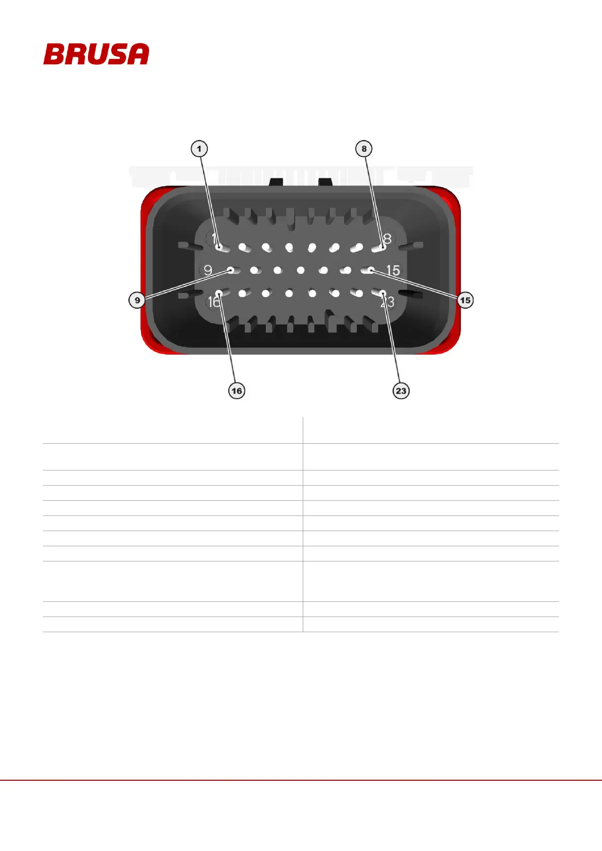
8.3 Pin assignment of control connector (device side)
Ground (Minus wiring system,
terminal 31, input range 6 – 32V)
+12 V (Plus wiring system,
terminal 30, input range 6 – 32V)
Enable (Power ON, terminal 15, input
range 6 – 32V)
RS232 Transmit (9 pole D-Sub pin 2)
RS232 Receive (9 pole D-Sub pin 3)
RS232 ground (9 pole D-Sub: pin 5)
External shut down path 1
(Plus wiring system, terminal 30,
input range 6 – 32V)
External shut down path 2
(Plus wiring system, terminal 30
Input range 6 – 32V)
* = The connections must be wired for normal operation!
** = Programming of the inverter is necessary!