Technical data
and startup
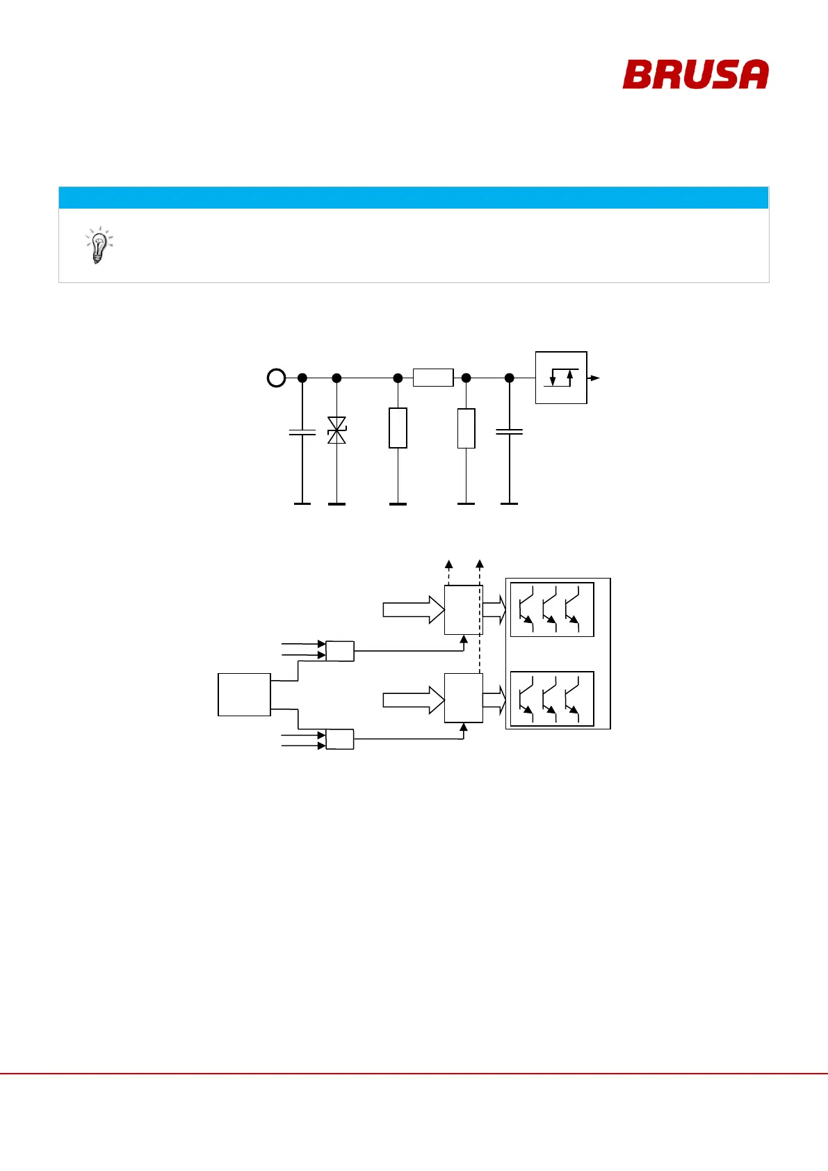
8.3.7 Pin 17 EXT AW1, Pin 18 EXT AW2 (External shut down path 1 + 2)
These pins must be active for the basic functioning of the inverter.
This function is also intended as an additional safety installation. The shutdown takes place
redundantly through this at the output stage drivers (see illustration).
If this function is not used, both pins must be connected with terminal 30!
Pin 17 EXT AW1
Pin 18 EXT AW2
To enable the output stage, pin 3 EN must also be high.
The both different circuits enable a redundant, direct switching off of the output stages.
The output stage can be released through higher-level control via these pins.
driver
stage
driver
stage