EasyManua.ls Logo

Brush Bandit 2900T User Manual

Brush Bandit 2900T
94 pages
To Next Page IconTo Next Page
Page #1 background imageLoading...
Page #1 background image
STUMP GRINDER
MODEL 2900T
OPERATING & PARTS MANUAL
ATTENTION:
Depending on what replacement
parts you are ordering, we will
need the following information:
GRINDER COMPONENTS
Serial Number
Model Number of Grinder
ENGINE COMPONENTS
Brand
Engine Serial Number
Engine Spec. Number
CLUTCH COMPONENTS
Brand
Serial Number
Assembly of Clutch
MANUFACTURED BY
BANDIT INDUSTRIES, INC.
6750 Millbrook Road
REMUS, MICHIGAN, USA 49340
PHONE: (800) 952-0178 IN USA
PHONE: (989) 561-2270 OR 561-2272
FAX: (989) 561-2273 ~ SALES DEPT.
FAX: (989) 561-2962 ~ PARTS/SERVICE
E-MAIL: www.banditchippers.com
Model No: _________________
Serial No: _________________
DEALER:
Name: ____________________
Address: __________________
City/State: _________________
Phone No: _________________
Delivery Date: ______________
Engine Make: ______________
Serial No: _________________
Clutch Make: _______________
Model: _________ S/N _______
Copyright 1/07
2900T

Table of Contents

Question and Answer IconNeed help?

Do you have a question about the Brush Bandit 2900T and is the answer not in the manual?

Brush Bandit 2900T Specifications

General IconGeneral
BrandBrush Bandit
Model2900T
CategoryGrinder
LanguageEnglish

Summary

INTRODUCTION AND SAFETY

MANUAL INTRODUCTION

Explains manual purpose and defines safety signal words.

SAFETY PRECAUTIONS

General safety instructions, PPE, and hazard warnings.

OPERATIONAL SAFETY WARNINGS

Warnings on operating conditions, slopes, refueling, and environmental hazards.

CALIFORNIA Proposition 65 Warning

Specific warning regarding diesel engine exhaust and its constituents.

EQUIPMENT IDENTIFICATION AND SPECIFICATIONS

SERIAL NUMBER LOCATIONS

Shows locations of serial and work order numbers on the machine.

MACHINE SPECIFICATIONS

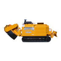
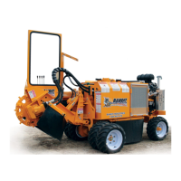
Details machine dimensions, weight, and key technical specifications.

DECAL LOCATIONS

Illustrates the placement of safety and operational decals on the machine.

CONTROLS AND OPERATION

CONTROL LOCATIONS

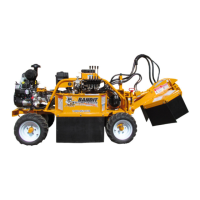
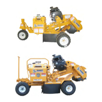
Identifies the primary controls and adjustment points on the machine.

CONTROL OPERATING PROCEDURES

Step-by-step instructions for operating machine controls.

MACHINE OPERATION STEPS

Daily start-up procedures and pre-operation checks for safe use.

CUTTING AREA GUIDELINES

Guidelines for optimal stump cutting technique and safety zones.

TRANSPORTATION PROCEDURES

SAFE TRANSPORTATION

Essential steps and warnings for safe machine transport.

LOADING AND UNLOADING

Procedures and precautions for safely loading and unloading the machine.

MAINTENANCE SECTION

GENERAL MAINTENANCE AND SAFETY

Overview of maintenance, safety during service, and break-in procedures.

DAILY START UP CHECK LIST

Daily checklist for machine inspection and maintenance.

BOLT TORQUE CHART

Specifies torque values for various bolts used on the machine.

PAINT CARE

Guidelines for cleaning, maintaining, and repairing the machine's paint.

BELT SECTION

BELT TENSIONING

Procedures and rules for proper belt tensioning.

POLY CHAIN BELT CARE

Information on poly chain belts, alignment, and tensioning.

SPROCKET ALIGNMENT AND INSTALLATION

Steps for aligning and installing sprockets for optimal belt performance.

LUBRICATION AND COOLANT

FLUID REQUIREMENTS

Details engine oil, coolant, track lubrication, and hydraulic fluid requirements.

REPLACEMENT PARTS SECTION

PARTS ORDERING INFORMATION

Information required for ordering replacement parts for the machine.

COMPONENT PARTS

UPPER FRAME COMPONENTS

Exploded view and parts list for the upper frame assembly.

CUTTER WHEEL COMPONENTS

Exploded view and parts list for the cutter wheel assembly.

HYDRAULIC COMPONENTS

Diagram illustrating the hydraulic system components and their connections.

SERVICE RECORD

SERVICE RECORD TEMPLATE

Blank template for recording machine service history and dates.

Related product manuals