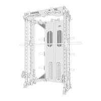
ASSEMBLY STEP 2
ASSEMBLY STEP 2 INSTRUCTIONS
- 8 -
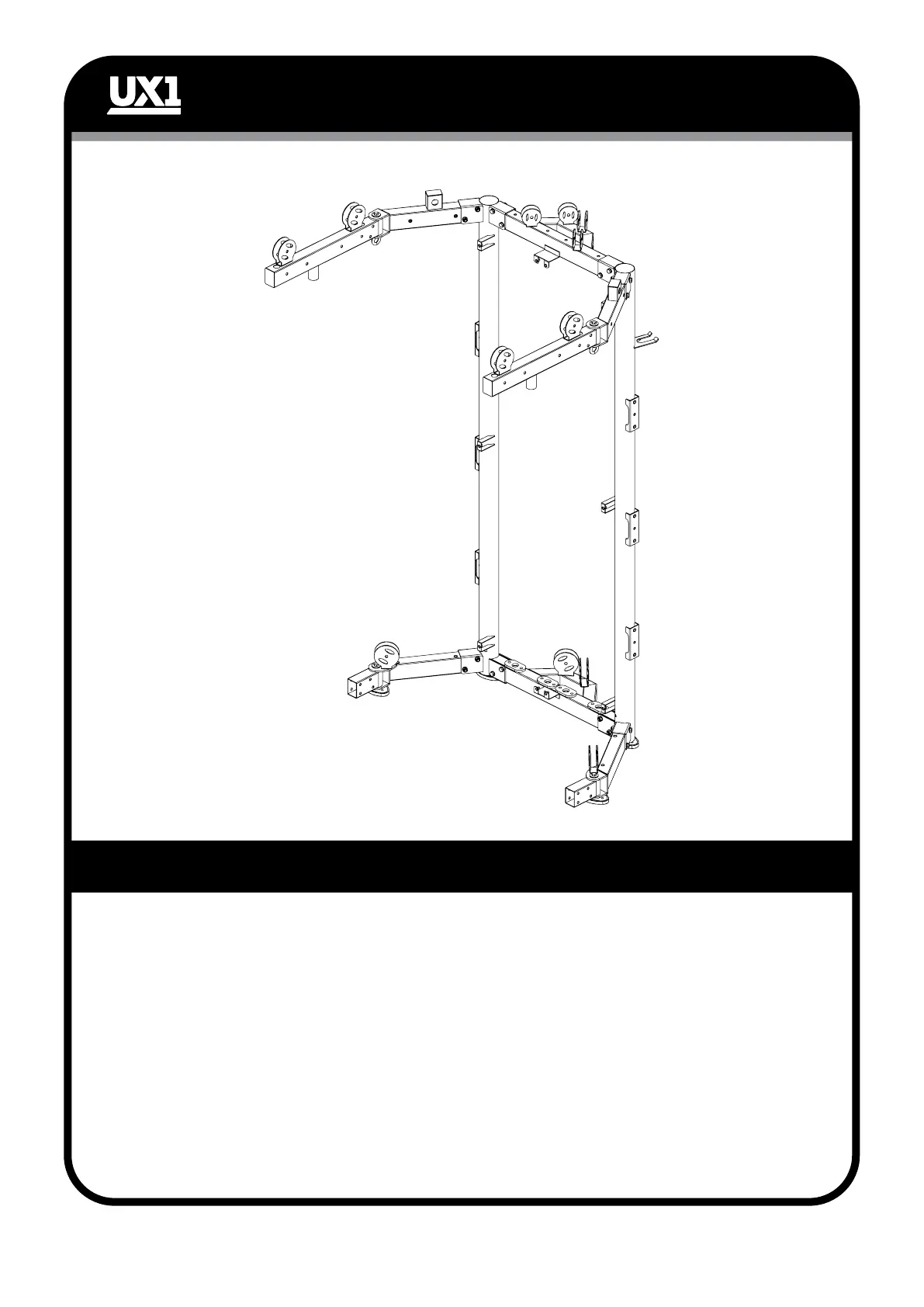
1. Connect side connecting frame right (10) with side connecting frame (16) and front
connecting frame right (11) with hexagon bolt (13), large flat washer (14), inner shaft (12).
2. Assemble the side connecting frame right (10) and side connecting frame left (16) to upper
frame right (3) and upper frame left (7) with M10*75 hexagon bolt (4), flat washer (6), lock
nut (5).
3. Connect upper side connection frame right (8) and upper side connection frame left (17)
to upper frame right (3) and upper frame left (7) with M10*75 hexagon bolt (4), flat washer
(6), lock nut (5).
4. Assemble upper side connection frame left (9) to upper side connection frame left (17)
with M10*20 hexagon bolt (13), Ø30*Ø10*3 large flat washer (14), Ø20*85 inner shaft
(12), lifting bolt (15). Assemble upper side connection frame left (9) to upper side connection
frame right (8) with M10*20 hexagon bolt (13), Ø30*Ø10*3 large flat washer (14),
Ø20*85 inner shaft (12), lifting bolt (15).