– 6 –
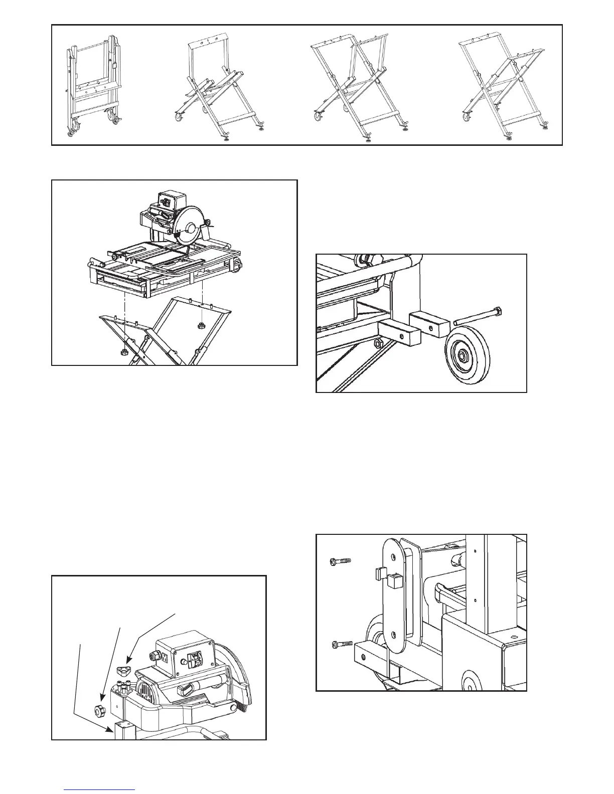
FIGURE 4
FIGURE 5
B. MOTOR ASSEMBLY INSTALLATION
STEP 1: Install the motor frame assembly into the
motor support arm (FIGURE 6).
STEP 2: Pre-fix the red motor frame locking knob into
the hole provided, as shown. This knob is also used to
fine-tune the alignment of the motor frame assembly.
STEP 3: Remove the rubber cap to expose hex nuts.
Firmly drive the three hex bolts into the motor support
arm with Allen key provided and secure the motor
frame locking knob.
STEP 4: Place rubber cap back over hex nuts.
Motor
frame
locking
knob
Rubber
cap
Motor
support
arm
FIGURE 6
C. INSTALLING UPPER FRAME
WHEELS
Secure the 4 in. wheels at the two ends of the base
frame with hex bolts and nuts, as shown (FIGURE 7).
FIGURE 7
D. INSTALLING THE CORD
COLLECTING HANGER / TOOL CADDY
Secure the hanger onto the motor support arm with 2
bolts (FIGURE 8). Place 2 wrenches in hanger and place
Allen key in opening provided.
FIGURE 8