1.9 BURNERS AND GAS TRAINS - ATMOSPHERIC BOILERS
1.9.1 GAS BURNER ASSEMBLY
The gas burner in theses boilers is an assembly
of burner tubes, along with the necessary fittings,
valves, and safety devices. The gas orifices in the
burners are sized to deliver the proper amount of
gas flow to achieve maximum boiler ratings at the
rated manifold pressure listed on the boiler
nameplate. Table 1.9A has average manifold
readings for the atmospheric boilers. A tapping is
supplied on the manifold for this purpose. A U-
tube manometer is recommended for accurate
setting of the manifold gas pressure. See "Start-
up and Operation", Section 2 of this manual.
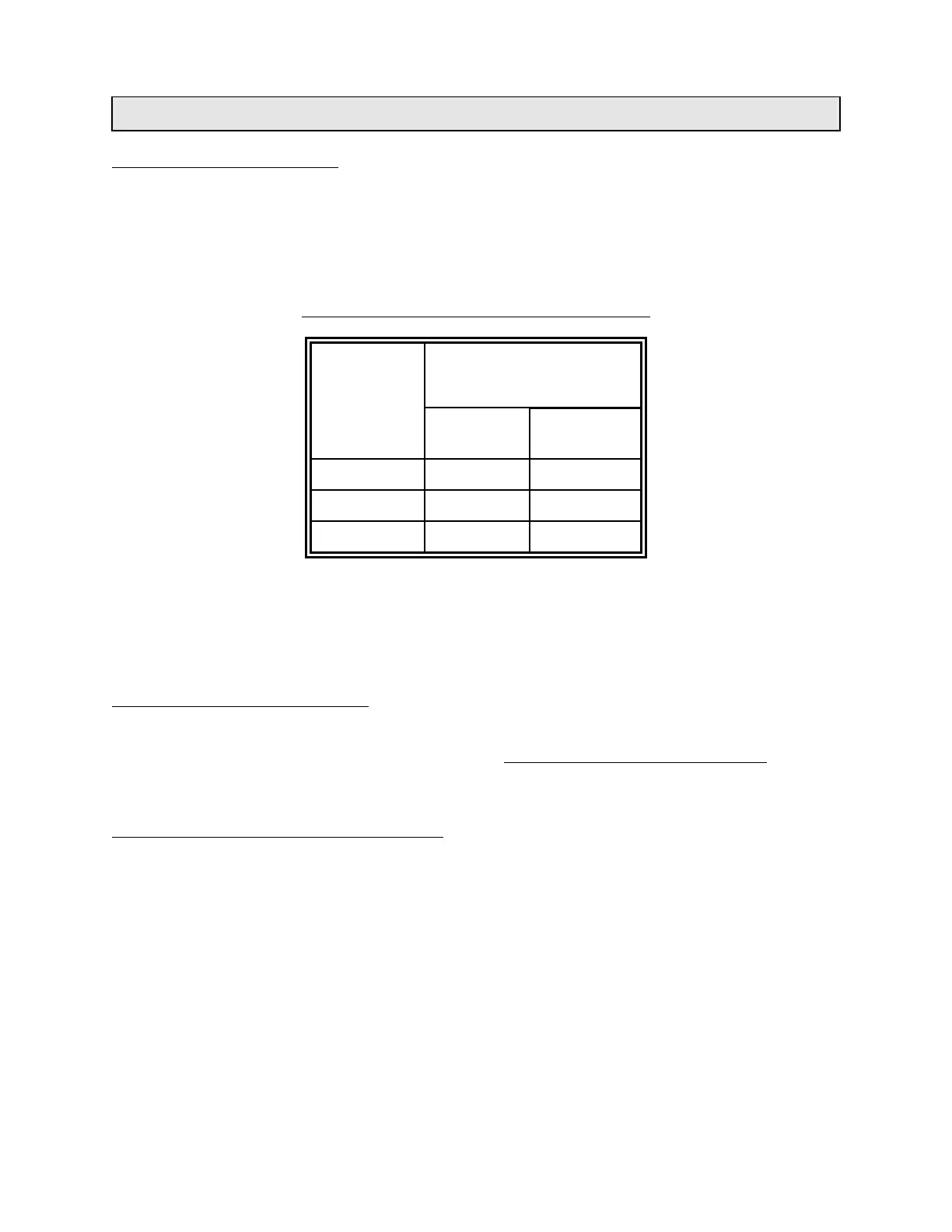
TABLE 1.9A: Approximate Boiler Manifold Pressure
BOILER
MODEL
MANIFOLD PRESSURE
LOW FIRE
(i.w.c.)
HIGH FIRE
(i.w.c)
F 1" 4"
CL 1" 3.5"
K 1" 4"
NOTE 1: Above gas pressures are for natural gas fuel only. For propane, high fire pressure is 11" w.c. and
2.5" w.c. at low fire.
NOTE 2: Reference manifold pressure on boiler nameplate.
NOTE 3: Above gas manifold pressures are approximate values only. Using a gas meter is the best way to
ensure correct input.
BOILER COMPONENTS - GENERAL
The boiler Equipment List in this manual lists the
gas train components. A description of the major
components follows. Refer to Lighting Instructions
and the manufacturer's literature on the
components included in the manual.
MAIN GAS COCK (MANUAL SHUTOFF VALVE)
The main shutoff cock is located in the gas line
ahead of the main gas pressure regulator. This
manual valve must be CLOSED during servicing
of the burners. DO NOT OPEN THIS VALVE IF
THE AUTOMATIC GAS VALVES ARE OPEN.
Refer to Section 2 of this manual and to Lighting
Instructions for proper use of this valve. A second
shutoff cock is sometimes supplied between the
burners and the automatic gas valves.
On some boilers utilizing combination gas valves,
such as the VR800 series, the main gas cock is
built into the combination gas valve body. The
VR800 combination gas valve series is included
in models VR800A, VR850A, VR844M, and
VR852M.
MAIN GAS PRESSURE REGULATOR
The main gas pressure regulator is located in the
gas train, downstream from the main gas cock.
This regulator maintains the proper constant gas
pressure to the burners. It may be adjusted to the
correct pressure by removing the cap on top and
adjusting the slotted screw CLOCKWISE to
INCREASE the pressure or COUNTER-
CLOCKWISE to DECREASE the pressure for
separate regulators. On combination gas valves,
such as the VR800 series, this adjustment is
exactly opposite. Pressure adjustments should be
made with a U-tube manometer attached to the
burner manifold test port to ensure accuracy.
On boilers utilizing combination gas valves, such
as the VR800 series, the main gas pressure
regulator is built into the gas valve body.