PILOT GAS PRESSURE REGULATOR
The pilot gas valves are electrically operated by
the boiler flame supervisory and operating
controls. Read carefully the enclosed instruction
sheet on the automatic gas valves as well as
Lighting Instructions.
Diaphragm type solenoid valves (such as the
V48A and V88A) require adjustment of the bleed
valve for proper operation. Refer to the literature
on the valve and Lighting Instructions.
The VR800 series combination gas valves
incorporate two main gas valves in the same
body.
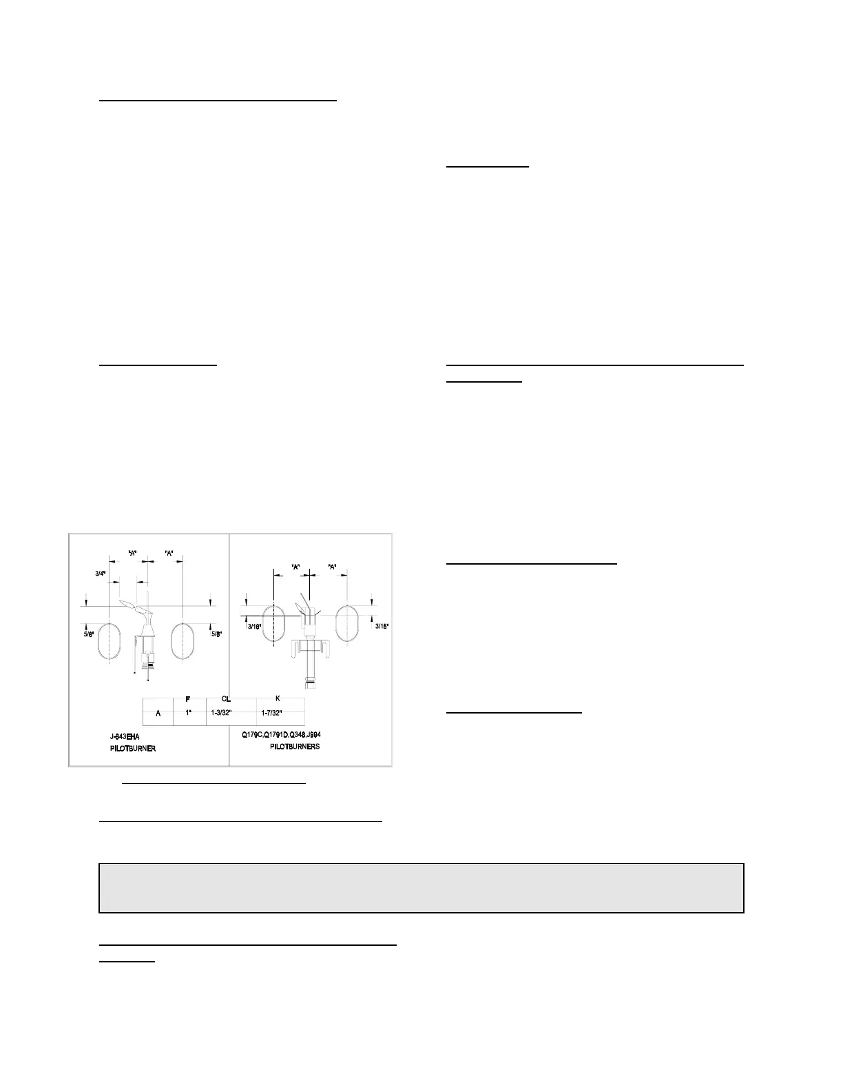
PILOT BURNER(S)
A Pilot Burner is installed in the burner assembly
to provide a source of ignition for the main gas
burners. Refer to Figure 1.9A for the proper pilot
flame. Refer to Lighting Instructions for pilot flame
adjustment.
The pilot burner gas supply line is taken ahead of
the main gas cock so the pilot may be lighted and
adjusted with this main gas cock closed.
FLAME SUPERVISORY SYSTEM - GENERAL
Flame supervision is provided by a pilotstat or
electronic control. These devices are intended to
allow gas flow only if the ignition source for the
main flame is a proven pilot.
PILOTSTATS
A pilotstat derives its ON-OFF action from a
thermocouple mounted in the pilot burner. When
the pilot flame encompasses the tip of the
thermocouple, the pilotstat will energize the main
gas valve after the thermocouple heats up.
Should the pilot flame be extinguished, the
pilotstat will revert to the OFF position, shutting
off the power to the automatic gas valve(s).
Carefully read the enclosed instruction sheet on
the pilotstat.
ELECTRONIC FLAME SUPERVISORY
CONTROLS
Electronic controls sense the flame using either a
flame rod (wire which conducts electrical current
though the flame) or and ultraviolet scanner (a
device which senses the ultraviolet light emitted
by the flame) to sense the presence of a pilot
flame. This type of control is used on all large
boilers and on some small boilers in place of the
standard pilotstat (thermocouple) device. See the
boiler equipment list for the equipment furnished.
FIG. 1.9A: Pilot Burner Flames
100% SHUTOFF SYSTEMS
When 100% shutoff is specified and furnished, a
pilotstat is installed on each pilot gas supply line.
This control is actuated by a thermocouple in the
pilot flame. It closes off the gas supply to the pilot
burner(s) if it fails to detect the presence of a pilot
flame. Electrically ignited pilots have an automatic
electric gas valve in place of the pilotstat.
BURNER SERVICING
On CL, K, and F boilers the burners may be
individually removed from the boiler for service.
The steel tubular burners rest on the burner
orifice at the front, and on a support bar in the
rear. On F series boilers, lift up the front from the
orifices and pull out. On CL and K series boilers,
lift up first the rear to release the pin. Then push
back to clear the orifice. Pull out.
1.10 PROCEDURES TO BE FOLLOWED BEFORE PLACING BOILER IN
OPERATION
1.10.1 HYDROSTATIC TEST OF BOILERS AND
SYSTEM
After completing the boiler and burner installation,
the boiler connections, fittings, attachments and
adjacent piping must be inspected for leaks by
 Loading...